
When most people think about portable military bridges they tend to assume the Bailey Bridge was the first, but this would be wrong, Charles Edward Inglis designed the first dry gap prefabricated military bridge in service with any Army anywhere in the world.
Although many Stock Spans were introduced earlier, they were used in construction (non-equipment) bridging rather than as a self-contained portable bridge.
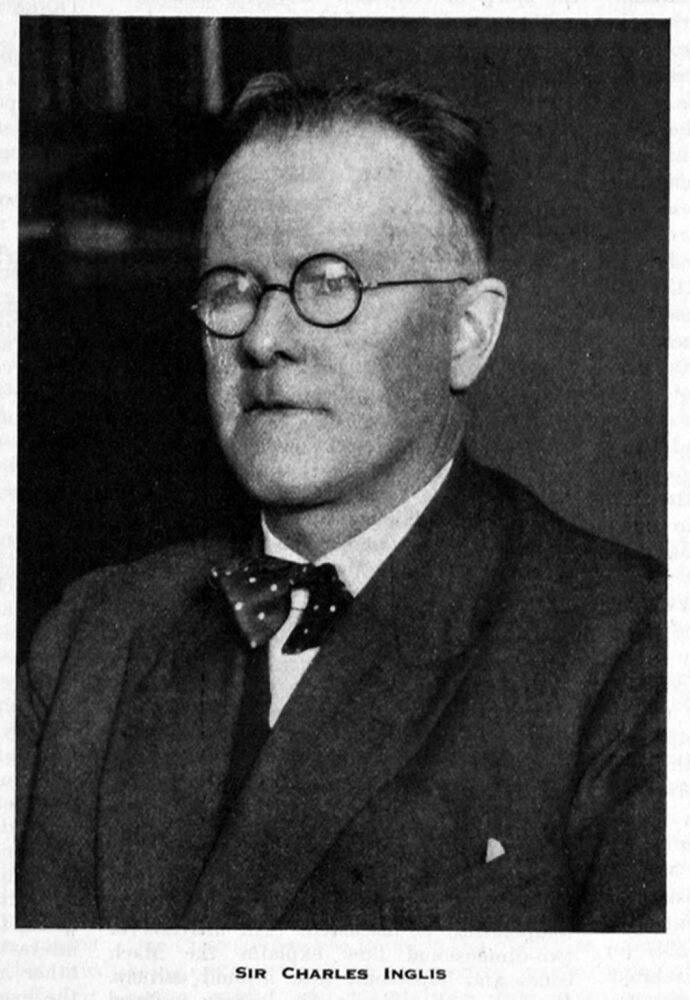
Charles Edward Inglis
Charles Edward Inglis (pronounced Ingles) was born in July 1875 to Dr Alexander Inglis and Florence Inglis (née Feeney).
After winning a scholarship to King’s College, Cambridge, studying both mathematics and engineering, he left academia to spend time as a bridge design engineer he re-entered academic life to become the first Fellow in Mechanical Sciences at King’s College in 1908.
In the early pre-war period, Charles Inglis was involved with the Royal Engineer section of the University Officer Training Corps and started the preliminary design work on a portable infantry bridge.
With the outbreak of war, he volunteered for service and was commissioned into the Royal Engineers and appointed to an instructor post at the School of Military Engineering in Chatham.
By 1916 he was responsible for the Corps bridge design and procurement section, continuing work on a number of different bridge designs.
After the war, he returned to Cambridge University as a professor of Mechanism and Applied Mechanics and, in 1919, was awarded an OBE.
After a long and distinguished academic career, he was due to retire in 1940, but the Second World War saw interest in his bridge designs rekindled. He was involved in military bridging for a second time.
Charles Inglis was knighted in 1945 and died on the 1st of April 1952, eighteen after his wife.
Read his obituary here
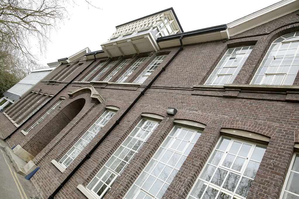
The Inglis Building at Cambridge University is shown below.
The Inglis Military Bridge (Various Designations)
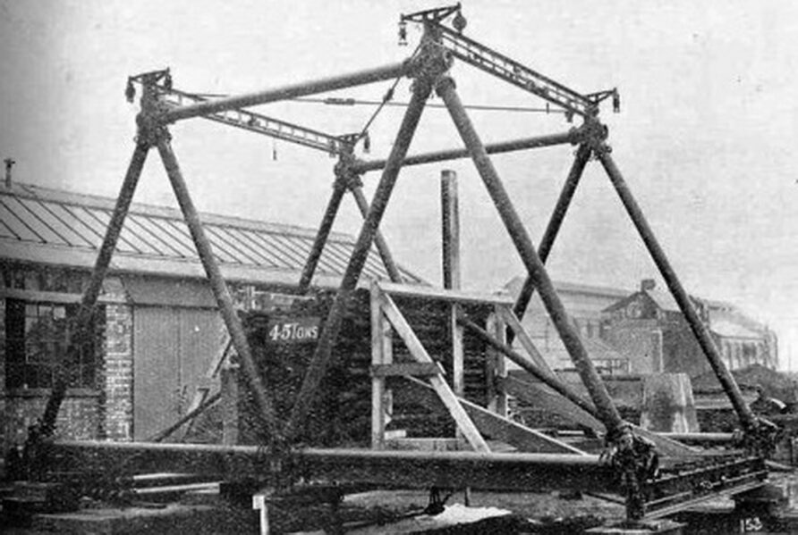
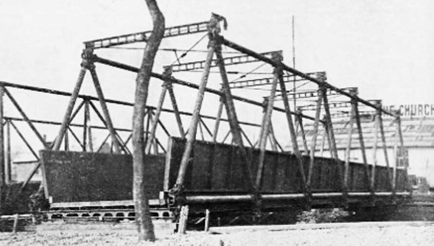
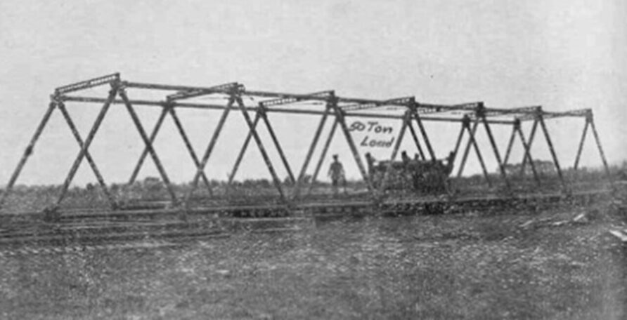
In the early 1900s, the British Army was experimenting with prefabricated portable bridges, the 1912 Bangalore Girder Bridge being a good example.
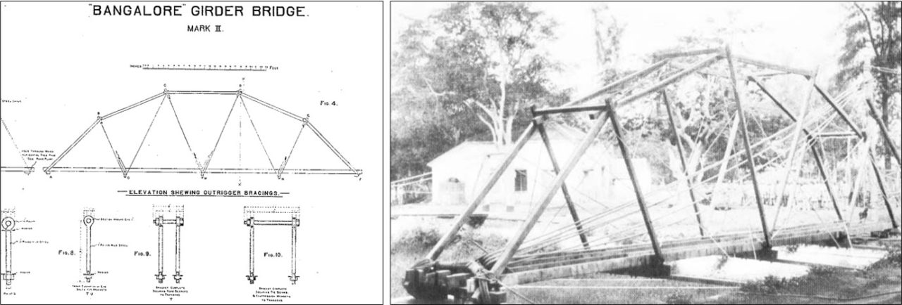
This design was produced by Major R.L. McClintock of Queen Victoria’s Own Sapper and Miners in India. Despite this, the norm was for heavy girder bridges to be fabricated on-site and swung out using a bridging derrick.
With the onset of WWI, much better was needed.
Inglis Portable Military Bridge — Light Type
The first Inglis bridge stemmed from work carried out in 1913 on an infantry bridge.
His obituary mentions this early period;
He had been an officer in the University O.T.C., and had noticed how on field days the engineering section had to stand about for hours with nothing to do. So he designed a bridge which they could put up and takedown in the course of an afternoon. An inspecting officer noticed it, and said, ‘If you’re making anything for the army, keep it simple – no complicated gadgets
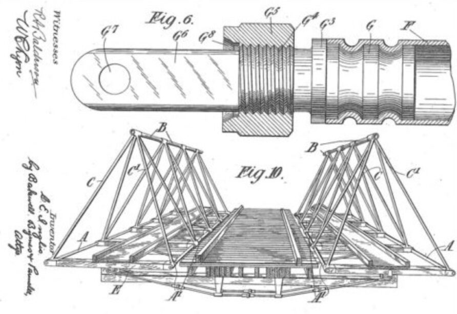
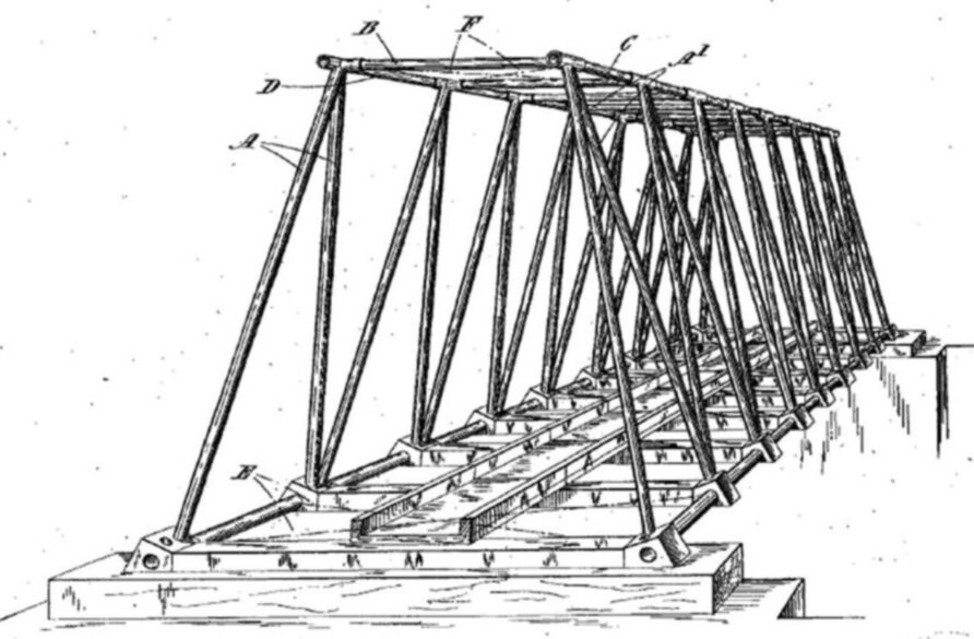
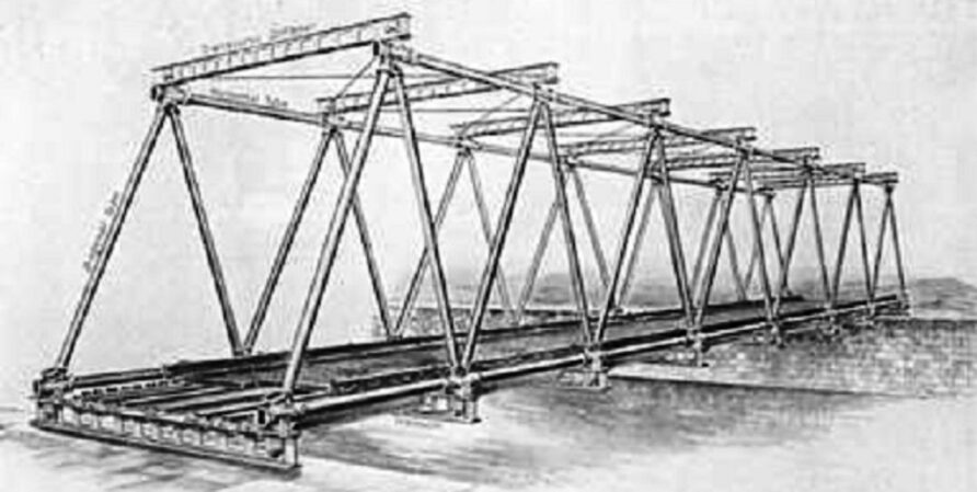
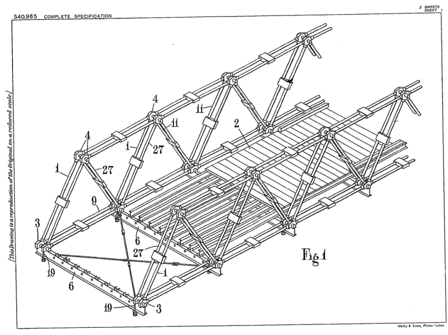
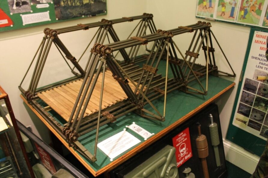
Officially called the Inglis Portable Military Bridge — Light Type, it was generally known as the Inglis Pyramid Bridge.
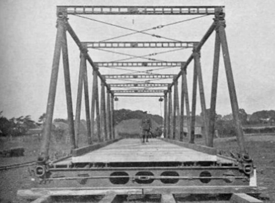
As can be seen from the diagram below, the Warren trusses were angled in and secured with a single tubular top chord placed in compression.
The bottom tubes were in tension and several trusses supported the single gangway.
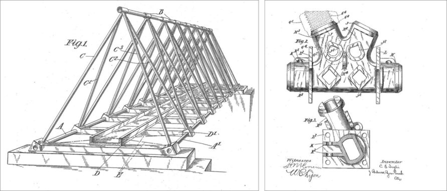
Although the transoms were heavy at 198 pounds (89.81 kg) each, the tension tubes were very light (similar to scaffold tubes) and this, coupled with the simple construction technique, enabled a 108-foot-long bridge to be completed in less than 15 minutes.
Originally intended only for infantry and able to carry single-file infantry over a 96-foot span.
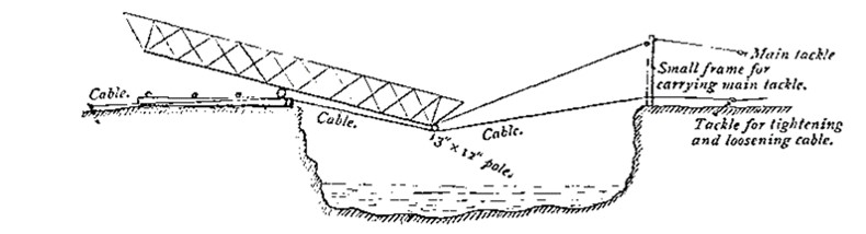
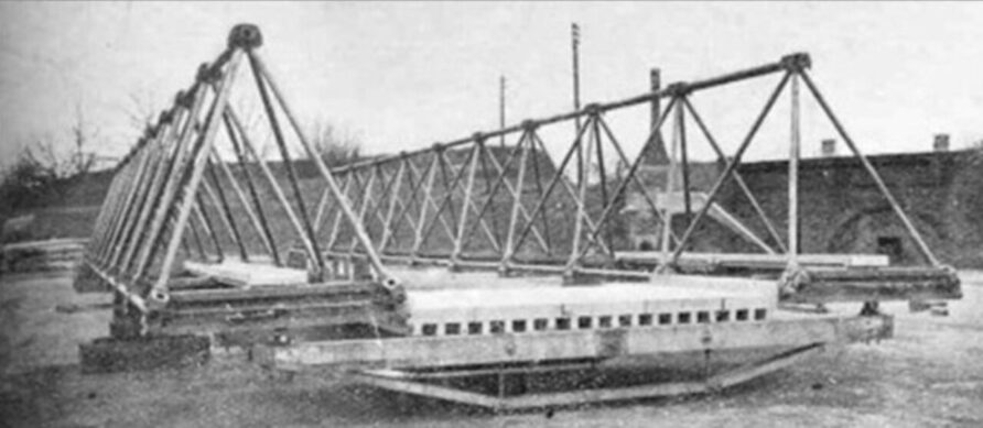
A two-wheel trolley was used to assist in construction, with the bridge being initially constructed parallel to the gap. Once complete, the bridge was swung over the gap, with the construction team providing the cantilevered weight.
10 sets were ordered for use in France.
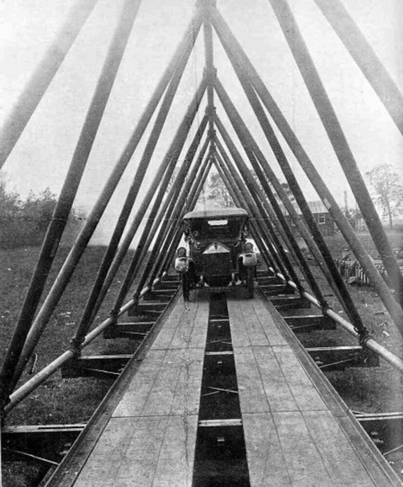
It was also possible to carry 3-ton vehicles by keeping the centres less than 16 feet (ca. 5 m) apart and combining two bridge sets.
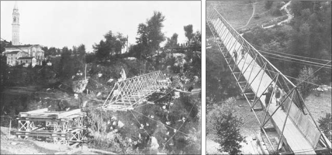
The first demonstration in France saw the Army Service Corps span a 108ft (ca. 33 m) gap in 13 minutes using an Inglis Light Type.
A truncated pyramid design version was proposed but never produced.
Inglis Portable Military Bridge — Heavy Type
Soon after, the BEF requested a modified design that could carry first-line transport vehicles up to 7 tons over a 96-foot gap.
Inglis responded by designing the Inglis Portable Military Bridge — Heavy Type, sometimes described as the ‘Second Pattern’
Instead of 8-foot tubes, the Heavy Type used 12-foot tubes and could carry loads up to 7 tons over a span of 96 feet (ca. 29 m).
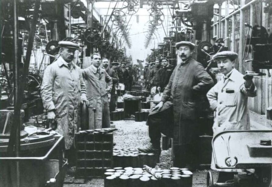
The tubes were fabricated at the Round Oak Steelworks in Brierley Hill, West Midlands which is now the site of the Merry Hill Shopping Centre, and the corner castings at the Kryn and Lahy Steel Founder and Engineers site in Letchworth.
Seventeen Heavy Type Inglis Bridges were ordered and delivered to France in 1916, although they did not see widespread use because the triangular construction meant tall vehicles could not traffic the bridge.
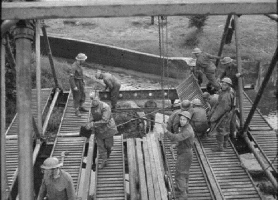
There is very little video footage of this bridge, perhaps this being the only one, at 5 minutes in, it shows the construction and launch sequence, especially the swing trolley

Survivors and Replicas
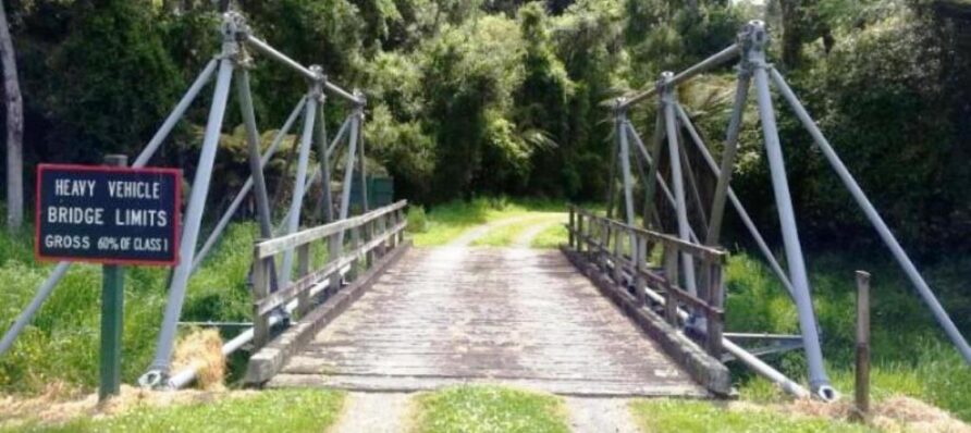
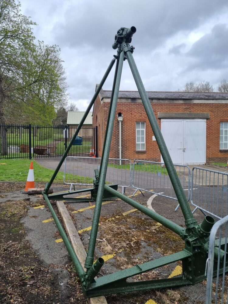
There is only one original Inglis Pyramid Bridge left anywhere in the world, and it is in the UK (to my knowledge).
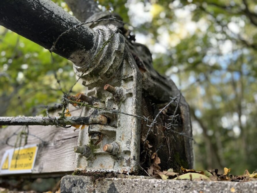
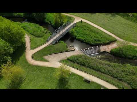
An Inglis Portable Military Bridge (Light Type) with pyramidal construction is in Aldershot, just off Laffan’s Road near Browning Barracks.
Laffan, of course, is familiar to any Sapper in the Hurrah for the CRE song, a former CRE.
In WWII, Malta Barracks was on the edge of Laffan’s Road on the edge of Watts Common and was used for Royal Engineer training as well as the nearby Hawley Lake. The bridge itself is between the Claycart and Farnborough Road bridges (see the Google map at this link).
It is used as pipe support, although I am not sure what the pipe carries.
This marvellous and historic piece of the nation’s military engineering heritage sits there alone and is largely unknown, although the Basingstoke Canal Society does have some information on it and the Pill Box Study Group has documented a nearby pillbox (funnily enough!)
The image below shows good detail of the junction box and how it was used to connect the tie rods and timber transoms.
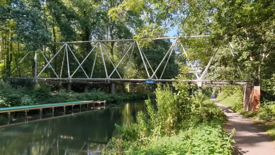
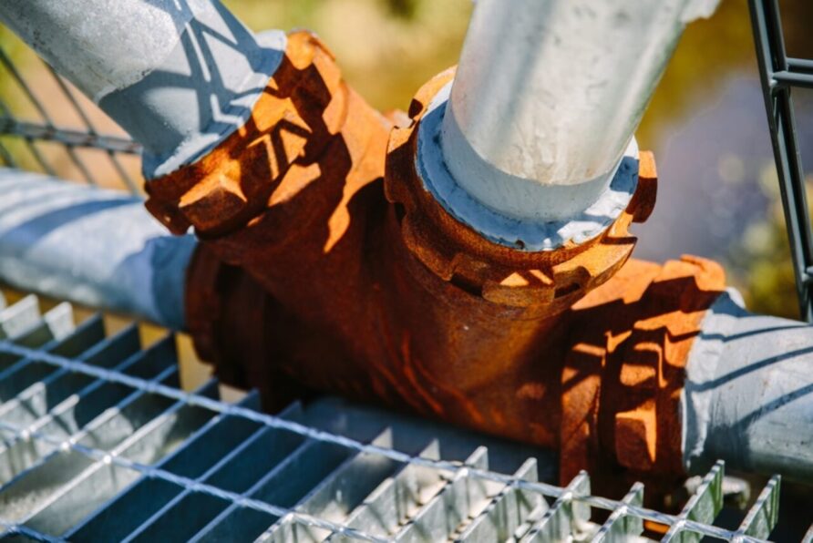
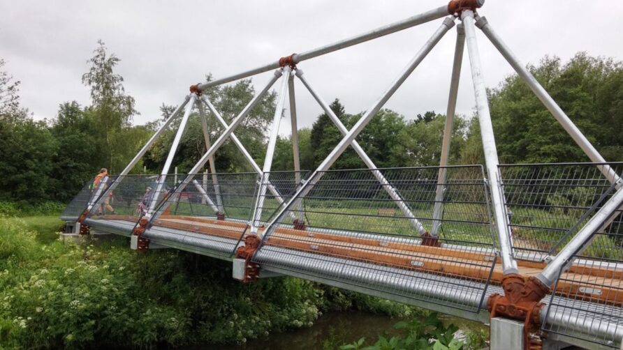
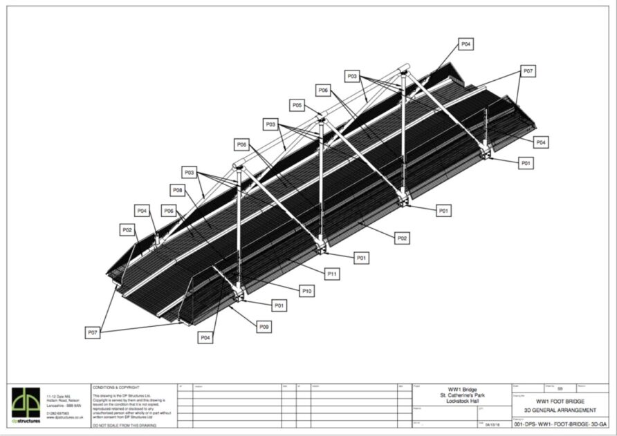
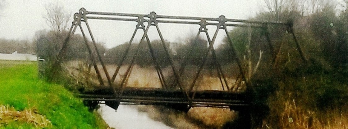
To commemorate men lost from the area during the First World War, South Ribble Borough Council commissioned DP Studios to recreate an Inglis Heavy Type Bridge for use in their Central Parks area
A few days earlier saw the unveiling of the continuation of the memorial area. The Inglis bridge erected over the River Lostock (or dandy brook) is based on a World War 1 design. In previous conflicts, rivers were spanned using boats and timber beams lashed together to form pontoons. Although much of the Great War was fought from the trenches, when the order came to advance, speed of movement became the key to success. A new type of bridge was needed. A modular bridge which was light and portable. Charles Inglis had already considered the issue and had a design ready to go. In the field the bridge was used to support front line troops. The sappers were often called upon to build bridges whilst under fire. The rapid deployment of the Inglis Bridge helped to reduce the casualties. As the fighting moved forward the sappers would erect a more permanent structure whereupon the Inglis Bridge would be dismantled and transferred forward to support the next offensive. The new bridge is based on the version developed by Charles Inglis during 1915 and referred to as the ‘Heavy Type. Every effort has been made to recreate the bridge as closely as possible to the original. However, for safety reasons, the following design changes have been introduced; the timber transoms (large members across the base) are replaced with steel, steel decking is installed and safety barriers added. The bridge is fixed and cannot be disassembled.
Images from the bridge
See it on Google Maps here
The Inglis Bridge Mark I and Mark II
With the emergence of the tank, it was clear that the existing stock spans and portable bridges would be unable to carry them, a new bridge was needed. By now responsible for all military bridging in the British Expeditionary Force, Charles Inglis was tasked by the Engineer in Chief to design an improved tubular bridge to carry heavier loads as typified by early tanks.
The resultant design took the tubular construction from the earlier Inglis pyramid bridges but used a more practical design with a lightweight pierced steel top web.
The junction boxes were still cast iron, and they used the same tubes as earlier designs, but the transom was of a similar design to the top web, pierced steel, not timber.
Mark I Inglis Bridge is often called the ‘rectangular type’ given the height to the top of the truss is longer than the base.
The Inglis Mark I was able to traffic Class A loads (17-ton axle load) over gaps up to 96 feet wide using a 12-foot bay.
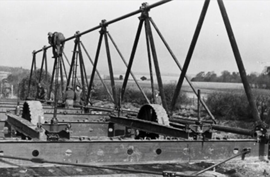
The image below shows an 84-foot MkI in use at la Motte in France, in April 1918.
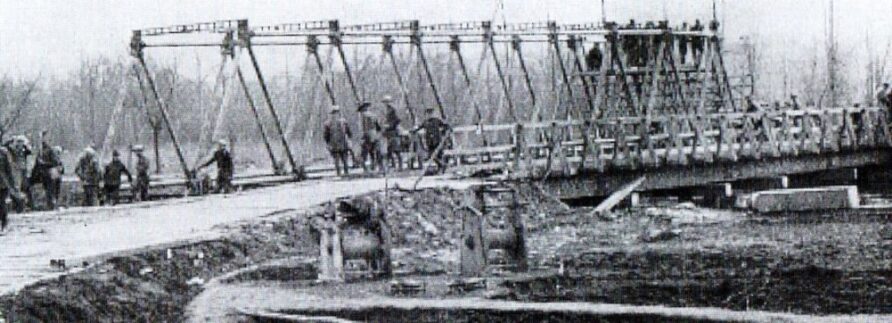
Canada in the Great War provides an excellent description of the build process;
A number of standard-span portable bridges, varying in span from sixteen to eighty-five feet, were stored at the base depots. These bridges consisted of loose members and were bolted with machine-turned bolts. They were, however, very cumbersome, and this rendered their erection slow. The weight was another disadvantage, e.g. the eighty-five-foot span was a single-way bridge and weighed sixty-three tons. Fortunately a new bridge, called the “Inglis Portable Military Bridge, Rectangular Type,” had been invented by Captain Inglis, R.E., and was adopted by the British Army. This bridge was the Warren girder type and was composed of a number of identical bays, each twelve feet long, twelve feet high, and twelve feet wide. It was designed to carry a dead load of eighty-four tons distributed over a clear span of eighty-four feet. Each part could be easily manhandled and the span could vary in multiples of twelve feet, e.g. sixty feet, seventy-two feet, eighty four feet, ninety- six feet, and one hundred and eight feet, to suit the gap. The bridge was built on blocks in skeleton form with a counterbalance arm and jacked up on to a two-wheeled trolley. It was then pushed over the gap, the counterbalance removed, then jacked down on the abutment, and the decking laid.
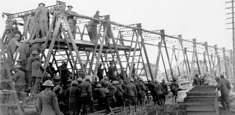
From the same Canadian journal as above;
On the 28th of September, 1918, a bridge of this type was erected complete over the Canal du Nord at Marquion in twelve and a half hours actual working time under severe shell-fire. A party of approximately two hundred sappers was employed on the construction of the bridge with the necessary approaches and abutments. The span was one hundred and eight feet clear and the safe distributed load fifty-one tons.
And here is a picture of them doing just that at the Canal du Nord in 1918
After arriving in late 1917 it was widely used in the final advance in 1918.
Although a big step-up in load-carrying from earlier designs, the unequal tube lengths could cause confusion during night builds and the new heavy tanks were still too heavy for it.
By the end of the War, the Inglis Bridge Mark II was under trial, essentially a strengthened Mark I with 15-foot bays.
A key improvement was a return to identical-length tubes and a deeper transom.
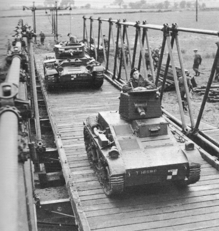
The Mk II (Strengthened Type) could carry a 35-ton Mark V** tank over a 105ft (ca. 32 m) span, it was also often called the ‘Square Type’
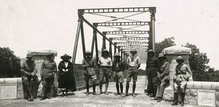
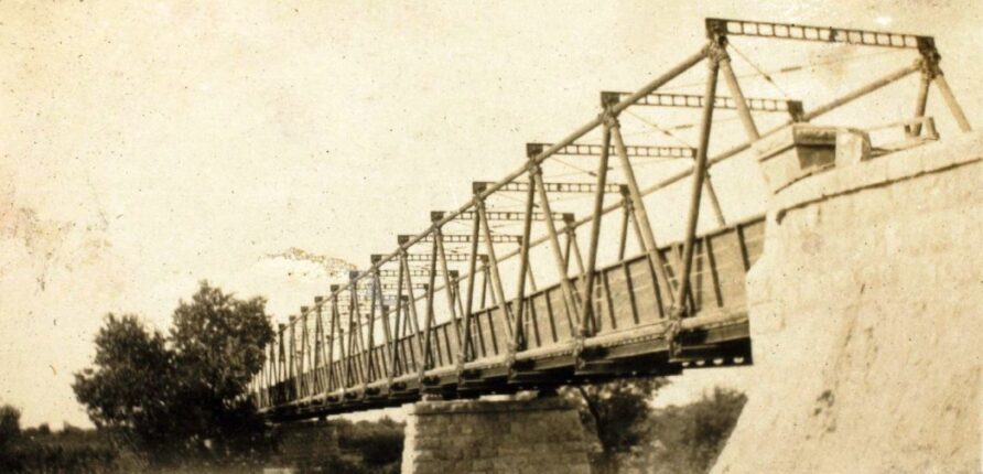
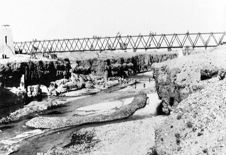
An Inglis Mark II was used to span the Jordan River in Palestine, this being called the Allenby Bridge
The Inglis Bridge was undoubtedly the best military bridge of the time with short construction times and high carrying capacity, but because of its tubular steel construction, was expensive, and was unable to traffic the common motor buses of the time.
As the war entered its final stages, it became ever clearer that the rapid bridging of tank obstacles and rivers/canals would be a vital element of armoured warfare and so in October 1918, three Royal Engineer Tank Bridging Battalions were formed, the first Royal Engineers armoured capability and the first in the world.
Each battalion was equipped with twelve Inglis Mk II (Strengthened) Bridges and several Heavy Pontoons. Each would also have 48 tanks equipped with the 21-foot Canal Lock Bridge.
The Canal Lock Bridge was also designed by Charles Inglis, aided by Major Giffard Le Quesne Martel.
Soon after the Armistice, two of the three Tank Bridging Battalions had been disbanded, but the remaining one was reformed under Martel to become the Experimental Bridging Company Royal Engineers at Christchurch
After the Great War, the Inglis Mk II continued to be used and developed into assault and floating bridges.
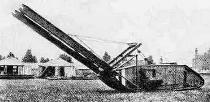
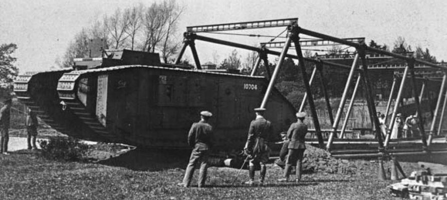
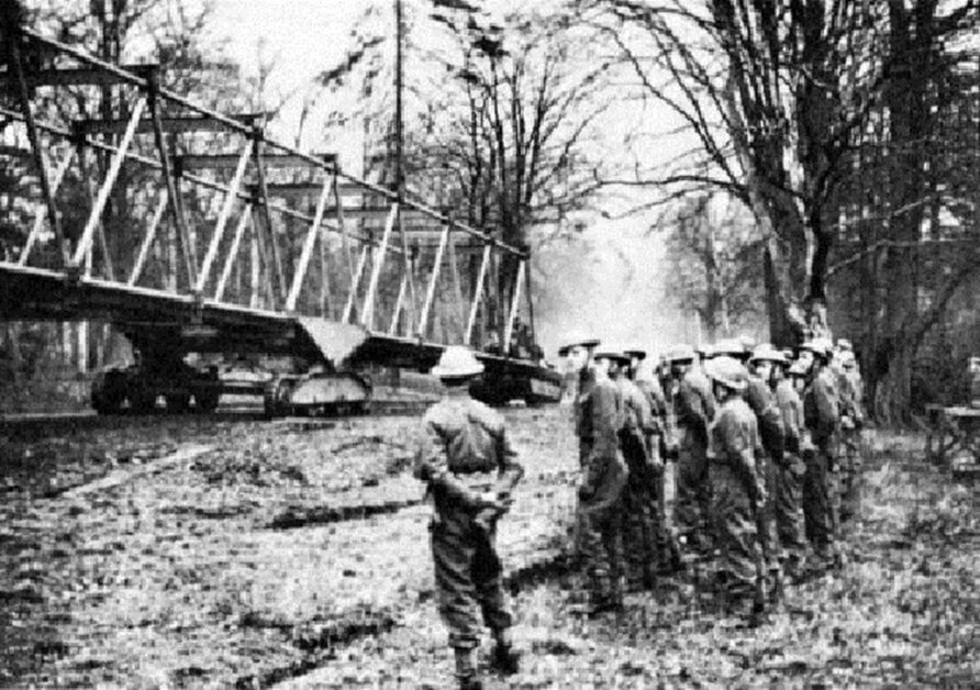
The Inglis Assault Bridge was a 135-foot-long span with a pair of idler tracks. The concept called for the Royal Engineers Tank to use its jib to push the assembled bridge over the gap.
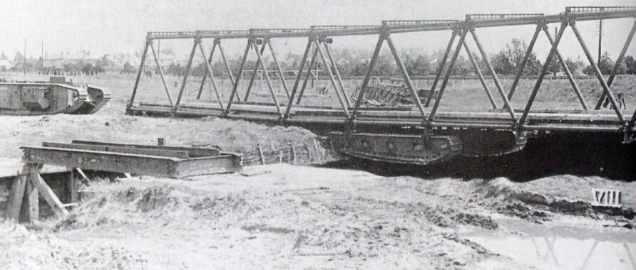
In less than a minute a 70-foot gap could be bridged without exposing any person to fire, the first true assault bridge to use a bridge of substantial length, over the standard 21-foot Canal Lock assault bridges of the time.
With the demise of the RE Tank (a modified Mark V** shown below), the Inglis Mk II Assault Bridge was not brought into service, but the experience would inform later assault bridge designs.
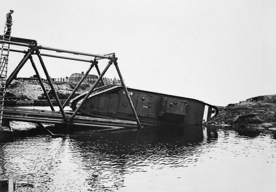
The use of the Inglis Mark I and Mark II in floating bridge arrangements was also trialled in the immediate post-war years.
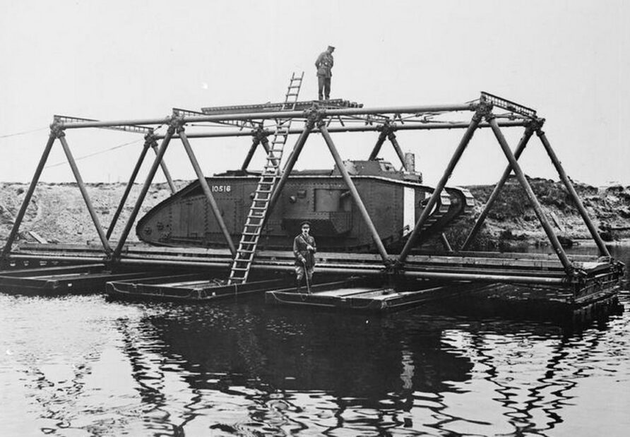
The Imperial War Museum has an online video of the Inglis pontoon and assault bridging at Christchurch in 1918, click the link below
https://www.iwm.org.uk/collections/item/object/1060000186
Inglis bridges were used throughout the empire, this one in Waziristan in 1919, for example.
After leaving the Army and returning to Cambridge after the war, Charles Inglis continued his close association with military bridging, designing the Inglis Heavy Floating Bridge for example.
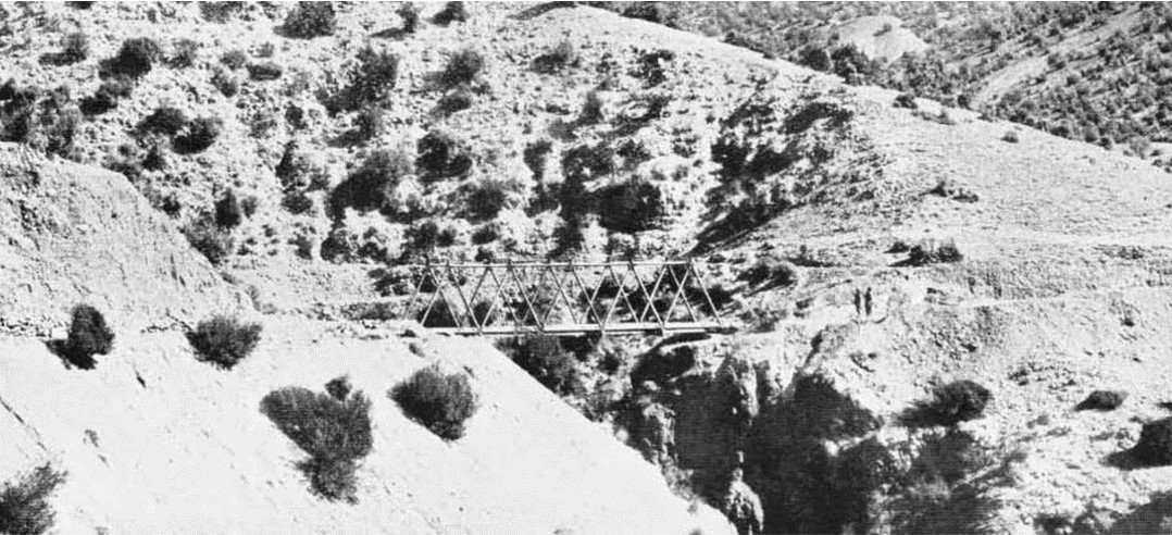
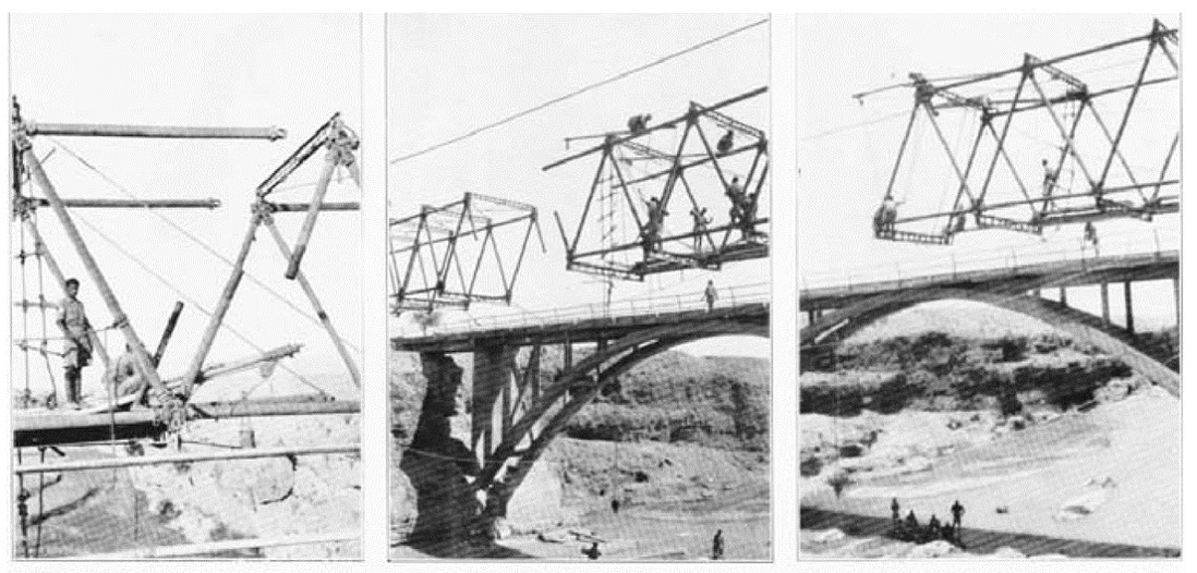
By the early thirties, the Inglis Mark I and Mark II were out of service, although they continued to be used for training and development and occasional use outside the UK, such as the Mk I Bara Bridge in the Peshawar District of India, near Bara Fort, in 1930.
The Mk I Inglis Bara Bridge was dismantled in 1933 as it had been superseded by a permanent concrete design (which can be seen in the background of the images below)
From the National Army Museum
The ‘Inglis’ pattern bridge, named after its inventor, Lieutenant later Professor Sir, Charles Inglis, (1875-1952) was constructed across the Bara River by No. 4 Field Company, King George’s Own Bengal Sappers and Miners. The specifications required that it be capable of carrying infantry in fours or 10-ton steam rollers, one at a time. Work began on 29 October 1930 and the bridge was open for traffic on 23 November. Photograph from an album compiled by C G S Clarke, 1st King George’s Own Bengal Sappers and Miners, 1930-1931.
The Inglis MkII was still in service at the outbreak of the Second World War and despite the existence of the Large and Small Box Girder bridges, the Inglis was retained because it was so flexible.
The Mark II did have one last hurrah as the Inglis Mobile Bridge, although, after extensive testing, it was not bought fully into service.
During this period, Charles Inglis also designed an improved crane system for building his bridges and a trestle for pontoon or floating bridges.
Survivors
There are still a few Inglis Mk I and II existing.
An Inglis Mark II bridge is in Monmouth over the River Monnow, it was built in 1931 to replace an old wooden bridge called the White Bridge that was built in 1905.
See the bridge on Google Maps here
Recently closed to vehicle traffic, it was maintained by the MoD because it marked the entrance to the headquarters of the Royal Monmouthshire Royal Engineers (Militia) at Vauxhall Field.
The Royal Commission on the Ancient and Historical Monuments of Wales has a small image gallery for the Inglis Bridge at Monmouth, and it is a Grade II Listed structure, the listed report describes its significance.
Military bridge. Erected by the Royal Monmouthshire Royal Engineers in 1931 and refurbished by the same regiment in 1998. Associated with the military camp at Vauxhall.
Adjacent interpretation panel was erected by the Institute of Civil Engineers in 2008 to commemorate the centenary of the founding of the Territorial Army. The First World War led to the rapid development of all forms of military bridging. Professor Sir Charles Inglis served as an officer in the Royal Engineers during the First World War and invented a lightweight, portable and reusable steel bridge.
Designed for rapid erection and deployment in combat conditions, it has prefabricated component parts and could be easily assembled in multiples of 15ft long sectional bays up to a maximum of 90ft in length with the minimum of mechanical assistance.
Mark II Inglis bridge utilising masonry abutments of an earlier wooden bridge. The Inglis bridge measures 90ft in length and comprises a single span and square section structure, formed from parallel longitudinal stringers, transoms, 9ft 6in wide wooden deck and upper and lower lateral bracing. The sides are constructed from equal-length tubular sections that are pinned into cast sockets to create a Warren Girder through truss bridge.
Listed for its special historic interest as a very rare example of an extant Inglis bridge and the only one known to be still in public use. Complete and with very little subsequent alteration, it represents an important stage in the design and development of temporary military bridging. A pioneering design in its own right, it was the precursor and inspiration for the better-known Bailey Bridge of the Second World War.
This may well be the only MkII existing outside a museum.
A Short Note…
Think Defence is a hobby, a serious hobby, but a hobby nonetheless.
I want to avoid charging for content, but hosting fees, software subscriptions and other services add up, so to help me keep the show on the road, I ask that you support the site in any way you can. It is hugely appreciated.
Advertising
You might see Google adverts depending on where you are on the site, please click one if it interests you. I know they can be annoying, but they are the one thing that returns the most.
Make a Donation
Donations can be made at a third-party site called Ko_fi.

Think Defence Merch
Everything from a Brimstone sticker to a Bailey Bridge duvet cover, pop over to the Think Defence Merchandise Store at Red Bubble.

Some might be marked as ‘mature content’ because it is a firearm!
Affiliate Links
Amazon and the occasional product link might appear in the content, you know the drill, I get a small cut if you go on to make a purchase
Download
You can also purchase this article as a PDF Download.
Each time I update it, you will be emailed a download link.
Back to the article…
The Inglis Bridge Mark III
At the outbreak of WWII, the Royal Engineers found themselves, like much of the British Army, without sufficient equipment for modern mobile armoured warfare and a widespread design effort was initiated.
Charles Inglis suggested a redesigned Mark II Inglis Bridge.
The Mark III Inglis Bridge was very similar to the Mark II but allowed the tubular trusses to be doubled or tripled up using a redesigned junction box.
With three trusses, the bridge was designed for Class 24 loads.
By using multiple trusses, the bridge would provide Sappers with the flexibility to avoid overbuilding.
Reverting to the 12-bay length of the Mk 1 meant the height of each truss was such that the Mk II top beams and sway bracing would not be possible if in-service vehicles were to traffic it.
As it was developed, some disagreement between Inglis and the EBE over test methods resulted in a test failure on 23rd January 1941.
An order for one hundred 120-foot sets had already been placed, so a quick solution was needed.
Overhead bracing was out of the question, so the solution proposed and accepted was to add a foot walk bracket to each end of the transom, shown in the image below.
A stronger transom was also used, note the smaller circular holes than those used in the Mk II
Diagonal bracing from the foot walk bracket to the top of each truss provided the required strength.
The image below shows the bracing and foot walk brackets on the triple truss configuration model.
Although the Mk III was an effective design, it was still expensive and was soon eclipsed by the Bailey Bridge.
Survivors
There are a number of Mk III’s still existing.
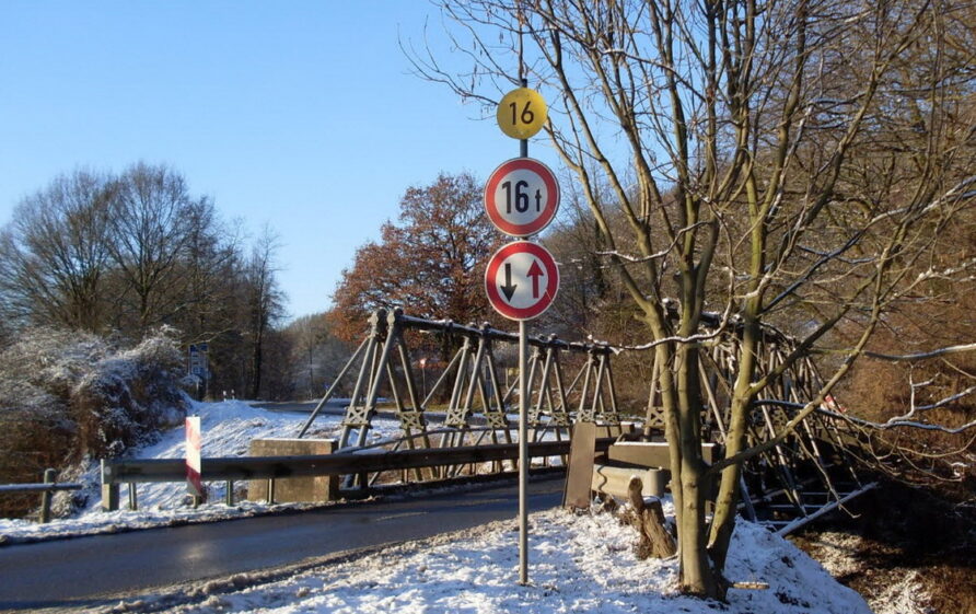
Some time ago, I received an email from Derek at the RE Museum (another fellow bridge enthusiast) about their efforts to identify a bridge in Emmerich, Germany.
I am a volunteer in the R E Museum, We received an e-mail inquiry from a man who lives in Emmerich, Germany asking for help to identify an Inglis bridge that was still in use over a river called The Wild. I have recently visited the bridge and found out it was built in late 1945, possibly by British Sappers, and has now been declared a war monument by the German Government. It is in excellent condition and is now restricted to 16 tons
And there it is, over the Die Wild at Spiker Weg is none other than an Inglis Mk III, click here to view it on Google Maps.
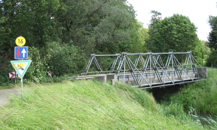
Like Monmouthshire and Basingstoke, Emmerich has a long history of association with the Royal Engineers, so it seems fitting for the three types of Inglis Bridge in each of those locations.
Thanks, Derek
A spot of additional Google Fu reveals what looks like another MkIII Inglis but without the additional trusses.
This one is in New Zealand at the Simpson Domain campsite erected by the Rangitikei County Council in 1985.
The Doncaster Inglis
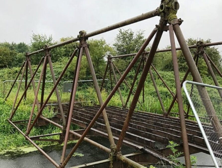
An Inglis Bridge was recently discovered at the former RAF Sandoft
The local branch of the Royal Engineers Association (REA) and the Royal Engineers Museum were enlisted to preserve and transport it to the RE Museum.
The Highways Agency and local Water Board gave permission and wheels set in motion to rescue this rare item of UK military heritage.
One of the last military bridges installed to form access to RAF Sandtoft, a Second World War airfield, has been removed after it was installed sometime in 1943/44.
The Inglis Bridge, which is believed to be the only known surviving Mark 1 version, has been removed from over a 7m wide watercourse to the north of the M180 in South Yorkshire. The bridge which has not been used since the end of the Second World War was the responsibility of Highways England and will be renovated by the Royal Engineers Association at the Army base in Nottingham. A partial segment of the bridge will be sent to the Royal Engineers Museum in Gillingham, Kent when renovations are completed.
Highways England project manager Russell Mclean said:
“This has been a fascinating project to be involved in. We were approached by the Royal Engineers Association earlier this year who were interested in renovating a segment of the bridge for their museum. “We were only too happy to help them with their request although the removal of the bridge did prove to be difficult as the bridge has been there for a long time so we weren’t sure how the structure was going to hold when we removed it. Luckily we were able to remove a large enough segment which can now be put proudly on display in the Royal Engineers Museum in Gillingham, Kent.”
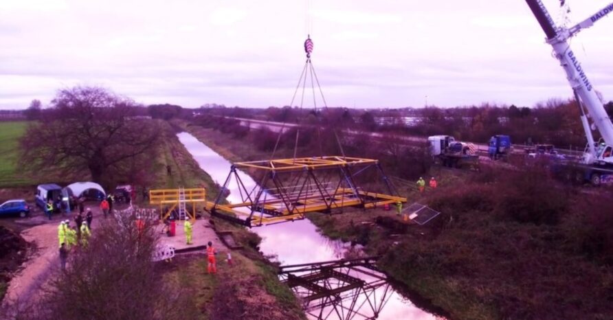
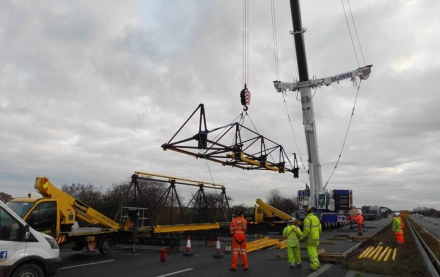
The 50 feet bridge was removed by a cradle that was bolted to the roadway of the structure and lifted by a 400 tonne crane. The bridge was then split into 2 so it could be transported to the army base. Members of the Royal Engineers Association were invited to the removal of the bridge.
Jim Johnstone of Doncaster Royal Engineers Association said:
“The members of the Doncaster Branch of the Royal Engineers Association have never been involved in a project of this magnitude. In collaboration with Mr James Brooke, the farmer, who kindly donated the bridge to us we feel that we are saving a piece of Corps history that otherwise would have been lost. From the members of the Branch we must also thank Highways England for the tremendous assistance given in the recovery of the bridge.”
Inglis bridges were the first modular bridges (that is a bridge which could be built, used, dismantled and built elsewhere) provided for access across rivers and gaps during the war as they could be constructed in a short space of time and could take a large amount of weight. They were usually assembled by a team of 12 men and a turntable. A counterweight was attached to the home bank side of the pre-erected structure which was then swung across the river to the far banking area.
Images from the removal below

Highways England also reported on the project.
This is great stuff; however, I do wonder if this is actually a single truss Mk III, not the Mk I as reported by various sources.
I have never seen any drawings or images of a MkI with the infantry footbridge and stabilising outriggers, only an MkIII.
The image above also shows the strengthened Mk III, the one with the small circular holes.
Furthermore, given the timeframe, when the bridge here was installed, in the mid-forties, the Mk I would have been long gone, but the MkIII would have been available, and more importantly, surplus to requirements given the introduction of the Bailey Bridge.
I could well be wrong, and the bridge in question might be a mix, certainly, during the war, anything surplus would have used.
A restored section of the Doncaster Inglis is shown below.
You decide!
Change Status
| Change Date | Change Record |
| 09/12/2017 | Initial issue |
| 18/03/2018 | Minor corrections and updates |
| 11/09/2020 | Additional information on the Inglis Bridge at RAF Sandtoft |
| 20/01/2021 | Added video of Light Type installation |
| 23/07/2021 | Added information on Bara bridge and format refresh |
| 03/08/2023 | General refresh and move from page to blog post format |
Further information
- Improved bridge trestle, abutment, landing stage, pedestal, or like framework
- Triangulated framework
- Improvements relating to triangulated frameworks and their application to the construction of bridges and the like
- Bridge Construction
- Improved crane suitable for erecting and launching bridges and similar girder constructions
- Improved junction-box for use in connection with triangulated frameworks
- Improvements relating to triangulated frameworks and their application to the construction of military bridges and the like
- Improvements in or relating to Joints and Joint-boxes for Tubular-members of Military Bridges and the like.
- Improvements in or relating to Military Bridges and the like
Read more

Discover more from Think Defence
Subscribe to get the latest posts sent to your email.


What I loved in the "American" video was the use of the bits of wood that they slotted onto the triangular sections to allow them to reach the top spars. Just goes to show that sometimes the "easy solutions" are the best. Anther great article TD. Keep up the good work
Some good news on the Inglis lightweight bridge crossing the Basingstoke Canal at Aldershot covered in this article: Historic England (HE) has given it a well deserved Grade II listing and therefore a good degree of protection from its removal – although, unfortunately, not necessarily a likelihood of any improvement to its condition:
‘Mk1 Inglis Portable Military Bridge (Light Type) over the Basingstoke Canal, Aldershot, Hampshire, Granted Listed Building Status – List Entry Number: 1489910.’
Apparently, the listing will be available for ‘Public Access’ on the HE website from 9th August 2024.
Incidentally, my understanding is that pipe it takes across the canal is for sewage.