Generic Vehicle Architecture (GVA) is an open, modular and scalable architectural approach applied to the design of military vehicles and systems.
The MoD has been at the cutting edge of vehicle electronics for several years, Generic Vehicle Architecture is the latest incarnation of this work. Generic Vehicle Architecture (GVA) is defined by the Ministry of Defense (MoD) to design electronic and power architectures, and Human Machine Interfaces (HMI) for vehicle electronics.
Generic Vehicle Architecture Origins
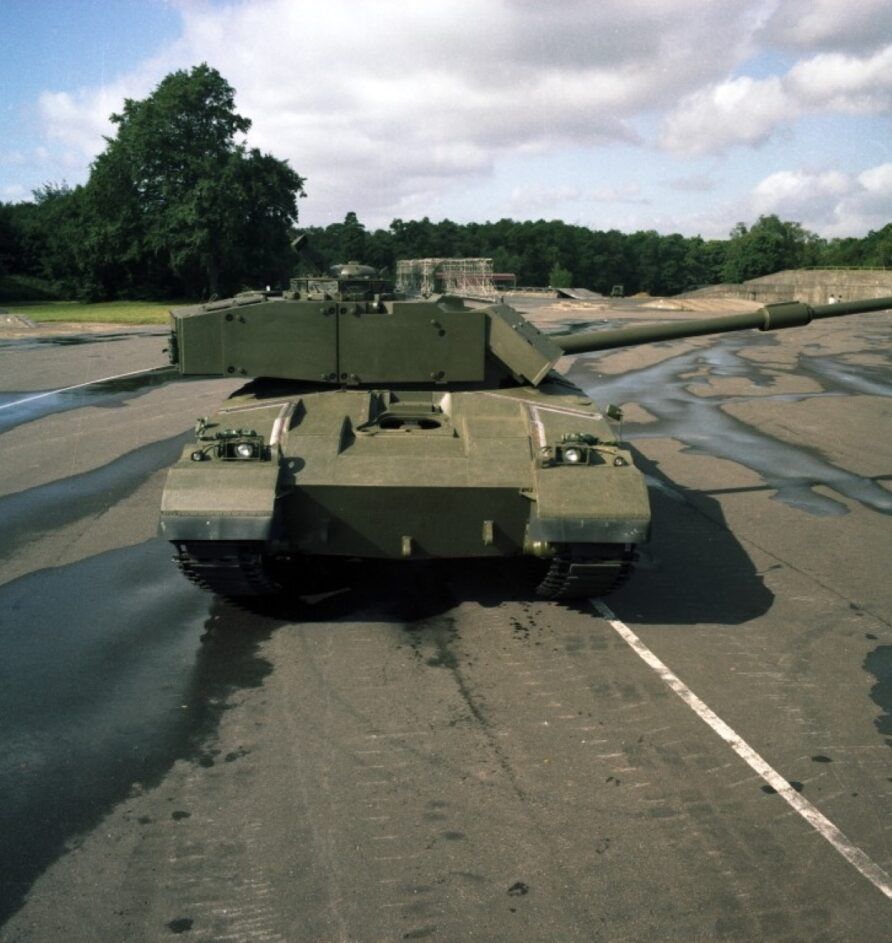
MBT-80 was to be the first armoured combat vehicle that would take full advantage of the microprocessor, and it was soon realised that its power distribution systems would need to be equally innovative.
Systematic Approach to Vehicle Electronics (SAVE)
This initiated work on the Systematic Approach to Vehicle Electronics (SAVE) programme at MVEE Chertsey.
SAVE defined standards for electrical and electronic distribution and physical characteristics for the power and electronic systems that would exploit modern microprocessors whilst remaining operable in the harsh environmental conditions of the main battle tank to improve performance and reduce crew numbers
Modular Assembled Vehicle Installation System (MAVIS)
The Modular Assembled Vehicle Installation System (MAVIS), or to you and me, a shelf, also defined the means by which electronics could be secured and mounted in vehicles.
Vehicle Electronics Research Defence Initiative (VERDI) and Wide Area Surveillance Automated Detection (WASAD)
With MBT-80 cancelled, the MoD built on SAVE and MAVIS with VERDI and VERDI-2, both significant pieces of research work carried out by MVEE and the industry.
In 1987, the Vehicle Electronics Research Defence Initiative (VERDI) built on this previous work. It examined how modern vetronics (a portmanteau of the words vehicle and electronics), sensors and communications equipment could be exploited to improve performance and reduce crew numbers. VERDI was a technology demonstrator using an FV510 Warrior as the base vehicle.
Concluding in 1990, VERDI demonstrated several different technologies including data bus multiplexers, navigation, data fusion, positioning, display and engine monitoring.
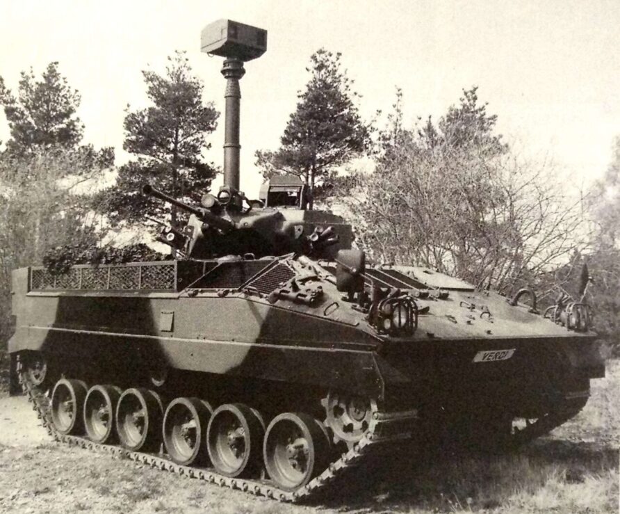
The benefits of mounting sensors on an elevating pneumatic mast from Clark Masts were also assessed. The demonstrator mast was equipped with a thermal imager and image intensifier. A crew of three was retained for this initial demonstrator but it was clear there was potential to reduce even this.
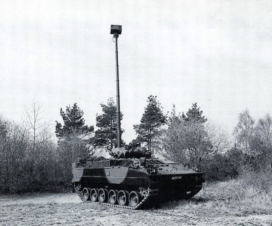
The Wide Area Surveillance Automated Detection (WASAD) project was built on earlier work at the Vehicles and Engineering Establishment (MVEE) which examined remote vision, vehicles with external cameras (instead of optical periscopes) and unmanned turrets. MVEE had concluded that the available technology of the period was not mature enough for adoption into service.
WASAD took another look, at newer technology. It developed a panoramic day/night vision system that included automatic target detection and recognition whilst on the move, connected via voice recognition to the fire control system on a modified Challenger 2.
WASAD had shown the potential of electronic systems’ integration in combat vehicles, while highlighting the need for greater standardization to ease implementation.
VERDI and WASAD had demonstrated massive potential and this resulted in a second phase project starting in 1993, VERDI-2. It was also designed to de-risk some systems thought likely to be included with the new Tactical Reconnaissance Armoured Combat Equipment Requirement (TRACER).
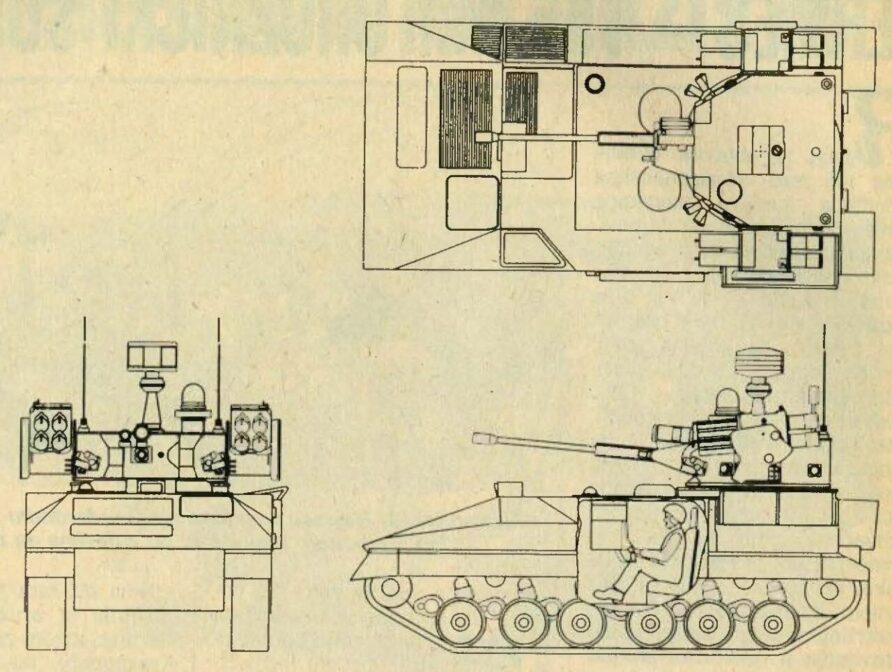
The VERDI-2 Warrior was designed to test 2-man crew concepts and the ability to manoeuvre using only indirect vision. It had a side-by-side crew station, each with two CRT displays that could show mapping information, GPS data, symbology, and other sensor information. VERDI-2 only had a crew of two, both side by side.
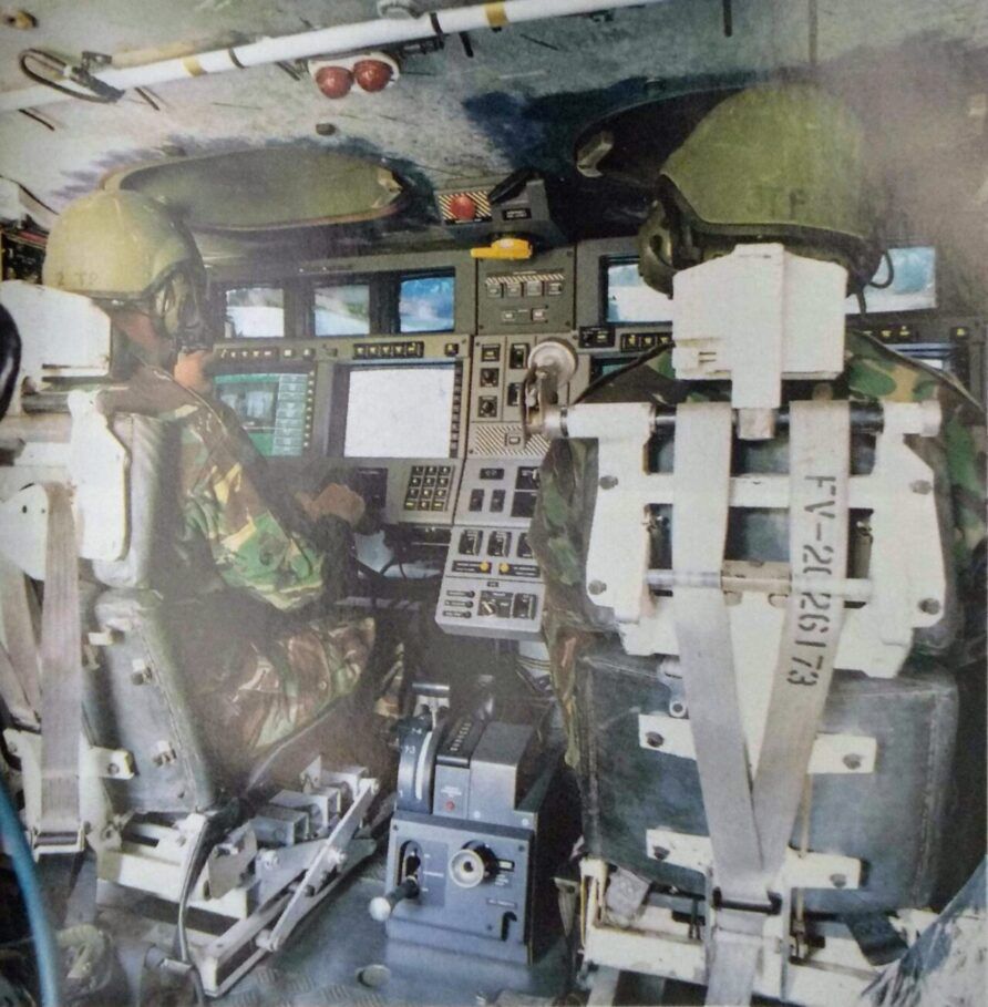
The sensor package was upgraded, using the automatic threat detection and identification systems from WASAD and this included audio warnings to the crew of potential danger.
The turret was also armed with an early version of the Starstreak High-Velocity Missile, Air Defence Alerting Device (ADAD) and a mock-up of the CTAi 40 mm cannon.
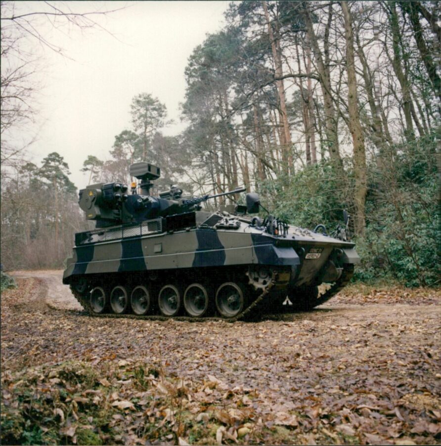
A new concept for VERDI-2 was to team the 2-man Warrior with a Troop Leader’s Stormer, communicating in real-time to establish a ‘recce team’. This vehicle acted as a communications and data hub and was equipped with additional data networking and processing equipment.
VERDI also demonstrated a remote surveillance remote-tracked vehicle called HARP that was carried as a demountable payload.
Trials were completed by Household Cavalry, their 1994/5 Journal describing the process, including this amusing comment on the fragility of early vehicle electronics:
The navigation systems fitted included a Global Positioning System, inertial navigation and a digital map, over which tactical overlays could be superimposed. The map showed your position all the time and gave you an 8-figure grid. A most useful piece of kit, it was impossible to get lost but of course, the system did fail on one occasion which meant we went around in a circle and ended up where we started facing the opposite direction which totally confused the boffins monitoring us.
One of the trial’s participants concluded;
The trial on Salisbury Plain was a success in as much as it proved a two-man crew can operate effectively for 48 hours in a closed-down environment, and it opened our eyes to what is available to the recce soldier of tomorrow. The main question to be answered before TRACER comes off the drawing board is what is the main role of recce? What does it need to do, collect information or destroy enemy light armour or both? Whatever the answers are, it must be smaller and faster. Let’s hope I’m still around to see it
The choice of Warrior for use as the base vehicle for the VERDI demonstrator seems to suggest an explicit recognition that CVR(T) did not have space or electrical generation capacity for modern sensors and computing equipment.
VESTA, VSI, VTID and VIVA
MBT80, VERDI and WASAD had proven the significant potential of electronics system integration in combat vehicles, but equally underscored the need for a standardised approach to implementation. In the early nineties, following the work completed on the VERDI programme, DERA initiated the Vehicle Standards Architectures (VESTA) project to provide the architectural foundation for the work completed by VSI.
In 1997, MVEE Chertsey and DERA then initiated the Vehicle Systems Integration (VSI) programme. VSI was a broad church, participants included the defence establishments, MoD scientists, academia, and industry.
The VSI website describes the aims of VSI;
- The identification and evaluation of open standards that will underpin the implementation of such architectures,
- Maintaining a close link between research communities and Industry to ensure maximum technology transfer,
- Maintaining a close link with the international vetronics community and, wherever possible, forming international collaborations that are of benefit to the UK.
VSI was used extensively during the development of the TRACER project, especially for the integrated sensor capabilities.
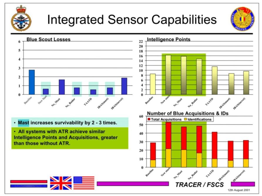
When TRACER was cancelled, the VSI programme continued with additional work sponsored by the MoD on the CANBus systems.
Platform Integrated Command and Controls System (PICCS) and Common Infrastructure for Battlefield Information Systems (CIBIS) were both attempts to standardise crew workstations, power, sensor, and other electronic systems integration and could be considered the building blocks for the later Generic Vehicle Architecture.
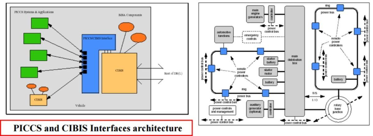
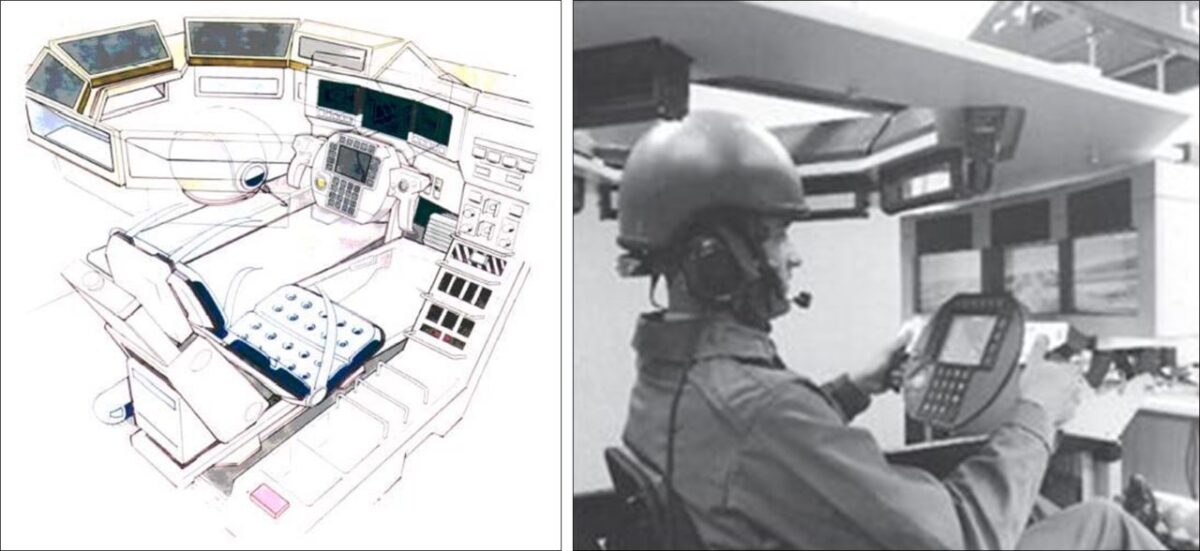
Alvis fitted a Scorpion with a CANBus controller and remote power switching, used to investigate system robustness and general suitability. The Alvis Vetronics Integration Demonstrator (AVID) programme was a Stormer fitted with an elevated sensor mast.
It was similar to VERDI in some ways, investigating integration issues, advanced sensors, navigation, and communications (the image below, bottom right, shows an AVID crew station)
The MRAV programme incorporated CANBUS systems, and the European HGV industry started to utilise CANBUS systems extensively.
With the cancellation of TRACER and MRAV, the research and integration effort moved on to the Future Rapid Effect System (FRES), specifically, the Electronic Architecture Technology Demonstrator Programme (TDP).
Unlike most of the FRES TDPs, the MoD let two contracts, one to BAE and one to Lockheed Martin. The outputs of this work, building on the work of VSI, SAVE, MAVIS, AVID and VESTA, formed the building block of Generic Vehicle Architecture.
In 2007, the Ministry of Defence (MoD) awarded a three-year £9.48 million research contract to a QinetiQ-led consortium for the Vehicle Technology Integration and Demonstrator (VTID) programme.
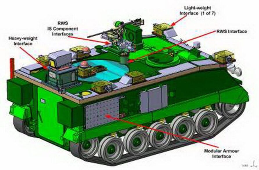
Other members included BAE, Thales, Ultra Electronics, SciSys, SVGC, Williams F1 and York and Sussex universities. VTID was designed to demonstrate a layered protection system for a test bed vehicle, a REME FV432, as it turned out.
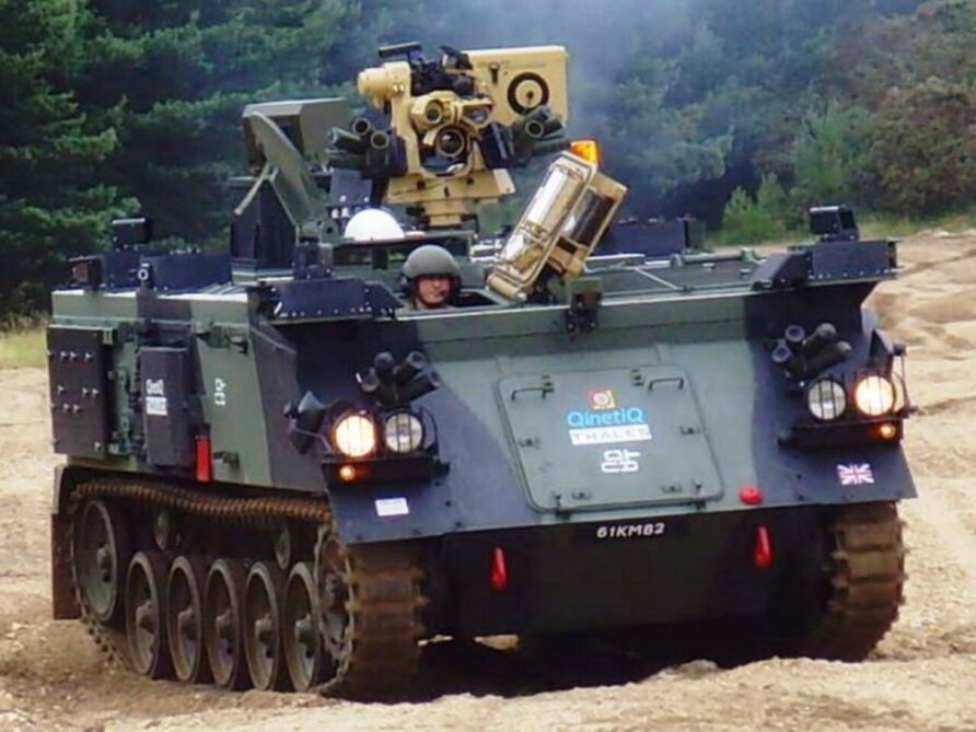
VTID was in addition to the FRES Integrated Survivability Technology Demonstrator Programme (TDP) and Electric Armour TDP awarded to Thales to Lockheed Martin respectively only a few years earlier. The aim was;
To quantify and demonstrate the utility of integrated survivability (other than physical armour) in respect of mounted close combat platforms, to counter the perceived threats in a range of representative scenarios
And the scope included;
- Integrated Survivability (IS) & Infrastructure Concepts
- Mission Modularity
- Modular Dependability
- Physical Integration of a range of technologies: LSA and Acoustic Sensors, LWR, RWS, Obscurants, etc
- Demonstration of IS concepts in different military scenarios
Janes reported the range of technologies likely to be considered;
Visual awareness and sensor suites, disrupters, interceptors, smoke deception systems, active camouflage and electric armour.
Although VTID was focused on protection, the systems needed an integrated information architecture and so much of the work carried out on the VTID project would also find its way into Generic Vehicle Architecture. Time-Triggered Ethernet was a particularly important recommendation.
The UK and Germany carried out a joint development programme on video interfaces for vetronics called VIVA and VIVA 2. VIVA 3 was also part of the VTID project that used video over Ethernet for the local situational awareness cameras and sighting systems.
In 2008 the Force Protection and Mission Systems Working Group were formed by the MoD and industry with the objective of addressing the increasingly difficult challenges of vehicle power management, man/machine interfaces and vehicle system architecture.
Def Stan 23-09 Generic Vehicle Architecture
GVA or Def Stan 23-09 is an open standard designed to place information at the heart of a vehicular system with the objective of creating a single, standard digital electronic and electrical architecture for UK vehicles.
DefStan 23-09 defines physical and communications interfaces on a vehicle to allow the interchange of equipment and provides definitions of the Human Machine Interface.
The official objective is;
The purpose of this Def Stan 23-09 is to enable the MOD to realise the benefits of an open architecture approach to Land platform design and integration, especially in regard to platform infrastructure and the associated Human Machine Interface (HMI) in order to improve operational effectiveness across all Defence Lines of Development (DLOD), reduce integration risks and reduce the cost of ownership across the fleet. This is achieved by mandating and applying the appropriate interface standards
Taking a list from the standard itself;
The nine basic principles of the GVA approach and Def Stan 23-09 are that they must:
- Take account of previous MOD investment;
- Be applicable to current and future systems;
- Use open, modular and scalable architectures and systems;
- Facilitate technology insertion (upgrade, update, replace, repair, remove and addition);
- Not needlessly implement in hardware any functionality that can be implemented in software;
- Take a ‘whole platform’ systems view, through life (including cost);
- Be done with industry and all relevant MOD stakeholders;
- Be MOD owned and maintained
- Specify the minimum necessary to achieve MOD’s desired benefits, avoiding unnecessary constraints in implementation.
Advantages of GVA include;
- Vehicle availability and reliability will be improved, instead of wasteful time-based maintenance intervals, conditions-based maintenance will be possible
- Availability-based contracts will be possible as vehicle usage data will be available on which to negotiate against
- Vehicle running costs can be reduced because condition-based information will again be available
- Processing and storage can be shared across multiple systems
- Vehicle capability can be increased as sensors could be shared and intelligence automatically gathered and presented
- Costs will be reduced by avoiding supplier lock-in, increasing competition and lowering the barriers to entry for smaller manufacturers
- Weight and power requirements will be reduced as equipment-specific cabling will be eliminated
- Reduced training
- Reduced space for ‘systems equipment
- Vehicles can be quickly reconfigured for different roles
- New sensors can be quickly fitted to vehicles to counter developing threats, this can be done quickly, in essence, plug and play for sensors
The MoD, QinetiQ and IBM, with a range of collaborative partners including Selex, IVECO, Supacat; Raytheon, RTI, L3 Communications, Paradigm, MaxOrd Ballistics, Aeroflex, Hypertac, Polar Com, Smiths Detection, Allen Vanguard, Britannia 2000, GE Aviation and many others published the standard in August 2010, with an agreed 18-month revision cycle.
Available here for all to read it is also important to understand the difference between GVA and the standard, GVA is the approach and the standard is one output from this.
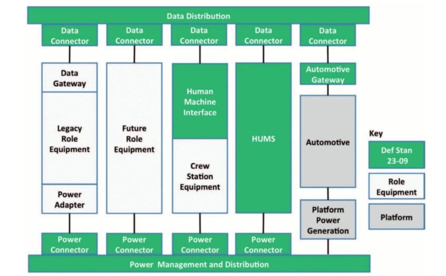
Although the physical and electrical connectors form a fundamental part of the standard, it is the use of a middleware model that enables equipment A to exchange data with equipment B, both from different manufacturers.
The Data Distribution Service (DDS) middleware system was chosen and the Land Data Model was subsequently released. The Land Data Model has been published (apart from certain restricted elements) and is freely available for suppliers, it is what is defined as a System Data Dictionary, published in standard Object Management Group (OMG) UML notation.
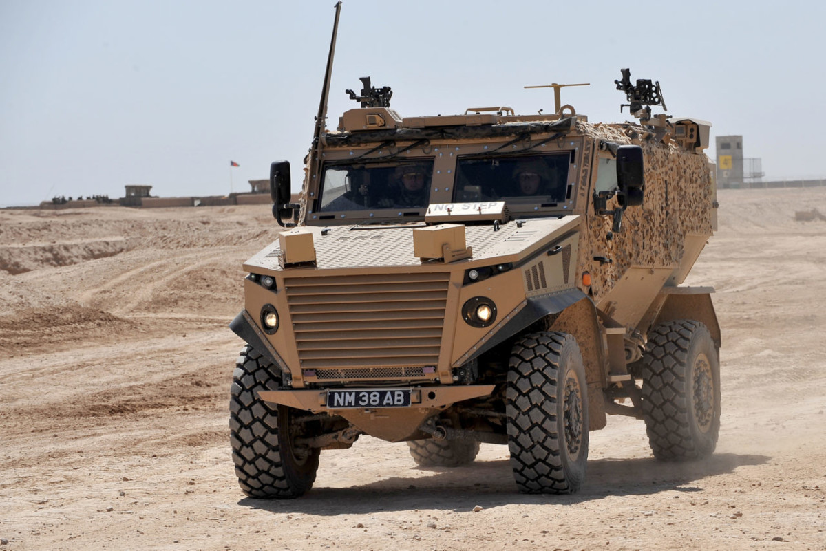
Thales, are the design authority for GVA on the first fully compliant vehicle, the Foxhound, this is of course a relatively simple vehicle, but it is a confidence-building evolution and therefore eminently sensible.
GVA also addresses legacy issues with a well-thought-through transition model, GVA compliant equipment can be used with legacy equipment through the use of gateways, firewalls, and adapters. Mastiff and Panther have GVA-compliant equipment integrated into a non-GVA-compliant system.
The current version addresses mechanical standards, power infrastructure, video, human-machine interface, health usage and monitoring (HUMS) and electronic infrastructure, but future versions might also cover communications, high-voltage power and electric drives.
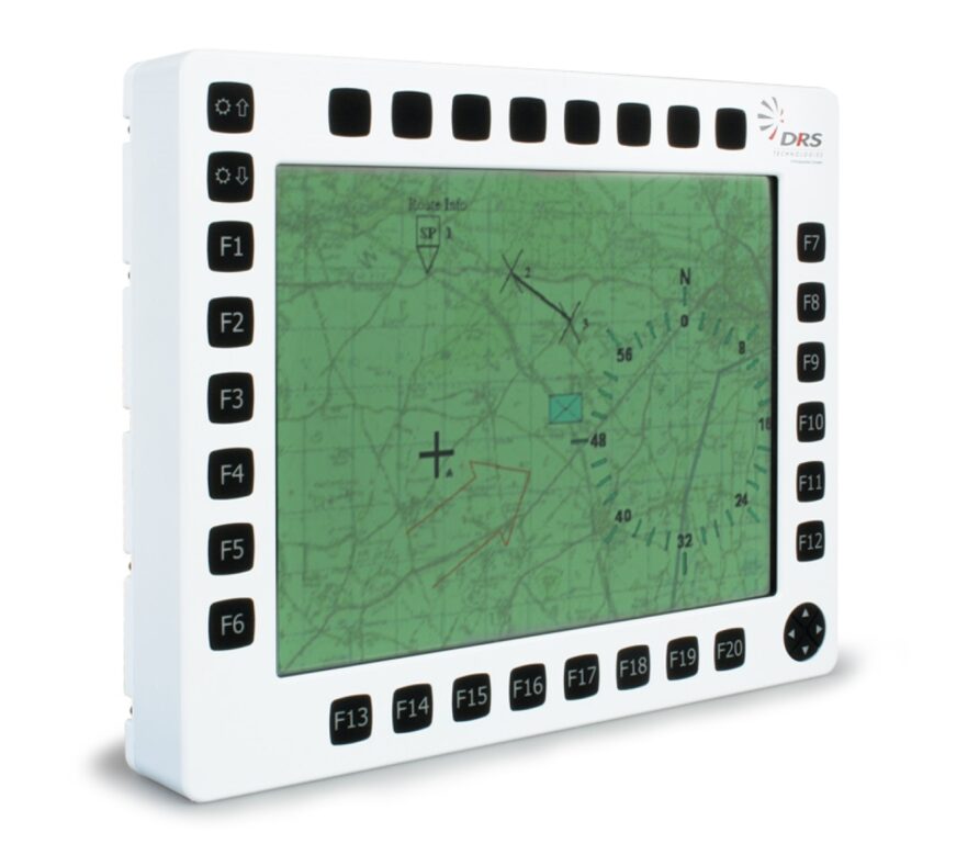
The three network types of safety-critical (TTP), deterministic (MilCAN) and high-speed (Ethernet). Other manufacturers are beginning to offer ‘GVA Compliant’ products, a clear sign of the standards’ maturity.
GVA is also joined by the Generic Base Architecture and Generic Soldier Architecture, more open standards, within the Land Open System Architecture (LOSA).
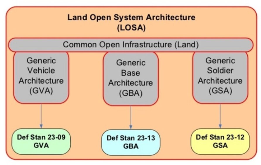
Although this may seem a rather dry subject, its importance should not be underestimated.
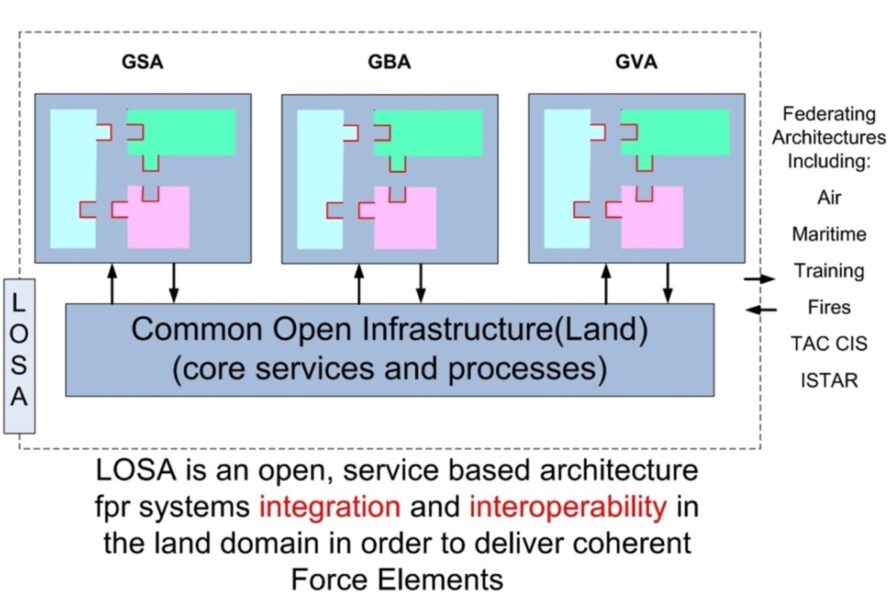
Def-Stan 00-82 (VIVOE, vetronics Infrastructure for Video over Ethernet) is in three parts; Guidance, Standards, and Protocols and Extensions for Audio and Acoustic Data. Video uses the RTP(V2)/SAP (Real-Time Protocol/Session Announcement Protocol), either compressed or uncompressed depending on vehicle needs and latency requirements.
GVA for Audio is an extension to the standard using the G.711 audio codec commonly used in telephony applications.
Although not part of GVA, MilCAN is a standardised means of implementing CANBus in military vehicles, read more here
Foxhound and Specialist Vehicles (AJAX) are compliant to near compliant.
Sadly, much work done on GVA and associated systems with Warrior CSP may not be realised with its cancellation. One of the most significant was the OpenLand360 software solution from CGI.
CGI OpenLand360 is a single software solution which integrates all hardware devices and systems within military vehicles. A fully GVA compliant Electronic Architecture initially designed and used on the UK Warrior vehicle upgrade – Warrior 2 programme.
CGI OpenLand360 has a single, consistent, GVA compliant crew-centric interface providing vital crew information about alarms, camera feeds, sight information, fire control, UK command & control, engine, power, Health and Usage Monitoring Systems (HUMS) and communications.
CGI OpenLand360 has also been used in concept demonstrations for mobile fires and for the control of semi-autonomous unmanned ground vehicles, all from the same single interface.
Click here to read the brochure
Manufacturers continue to develop and manufacture GVA-compliant systems.
Mildef, for example.

And General Dynamics
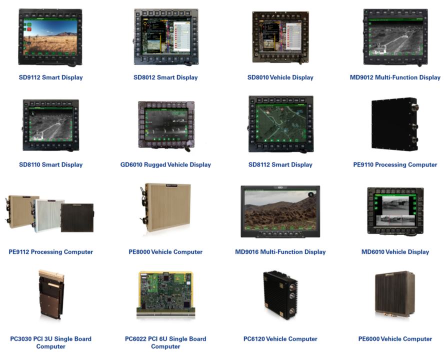
This is a good video from General Dynamics that shows a typical GVA display system.
This is an excellent overview
STANAG 4754 NATO Generic Vehicle Architecture
In 2012, the Organisation for Joint Armament Cooperation (French: Organisation conjointe de coopération en matière d’armement ;OCCAR) launched a project called Land Vehicle with Open System Architecture (LAVOSAR), the eventual winner being Rheinmetall.
The goals of the project were to study existing open standards and develop a strategy for the future.
LAVOSAR completed its work in 2014 and recommended that the UK’s Def Stan 23-09 Generic Vehicle Architecture be adopted as the NATO standard and extended.
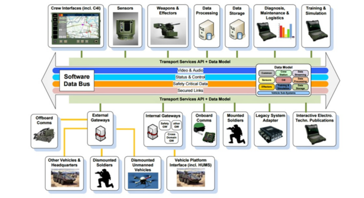
The European Reference Open Architecture Standard for a Modern Integrated Electronic Mission System in Military Land Vehicles’ (LAVOSAR II) project was completed in 2015 with recommendations for additional sections on logistics, maintenance and upgrading, training, and data exchange mechanisms.
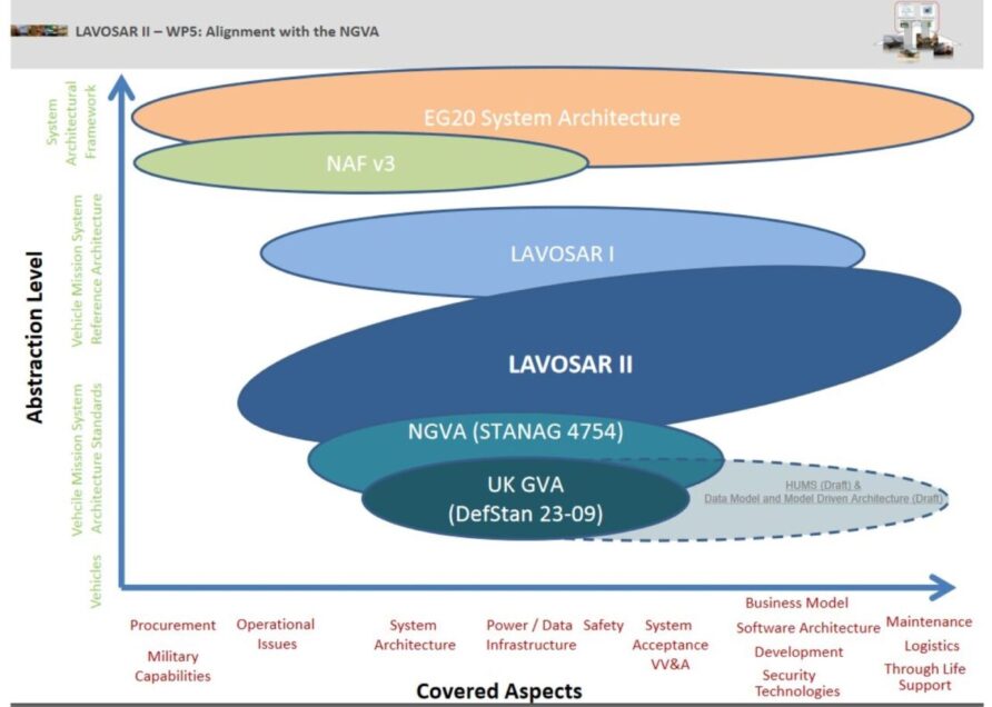
Further study in the form of the LAnd Vehicle Open Systems Standardisation (LAVOSS) Study Programme was also carried out by the European Defence Agency
NATO GVA (NGVA) is now known as STANAG 4754. NGVA is an extension of GVA that meets a broader set of requirements, including unmanned systems’ integration.
More information here and here
NGVA comprises a single STANAG document and seven associated Allied Engineering Publications (AEP)
- Architecture approach
- Power Infrastructure
- Data Infrastructure
- Crew Terminal Software Architecture
- Data Model
- Safety
- Verification and Validation
Before reading on, would you mind if I brought this to your attention?
Think Defence is a hobby, a serious hobby, but a hobby nonetheless.
I want to avoid charging for content, but hosting fees, software subscriptions and other services add up, so to help me keep the show on the road, I ask that you support the site in any way you can. It is hugely appreciated.
Advertising
You might see Google adverts depending on where you are on the site, please click one if it interests you. I know they can be annoying, but they are the one thing that returns the most.
Make a Donation
Donations can be made at a third-party site called Ko_fi.

Think Defence Merch
Everything from a Brimstone sticker to a Bailey Bridge duvet cover, pop over to the Think Defence Merchandise Store at Red Bubble.
Some might be marked as ‘mature content’ because it is a firearm!
Affiliate Links
Amazon and the occasional product link might appear in the content, you know the drill, I get a small cut if you go on to make a purchase
VICTORY Vehicular Integration for C4ISR/EW Interoperability
VICTORY is a US initiative designed to solve the same problems as GVA.
The Vehicular Integration for C4ISR/EW Interoperability (VICTORY) initiative was started as a way to correct the problems created by the “bolt-on” approach to fielding equipment on US Army vehicles. Implementation of VICTORY allows tactical wheeled vehicles and ground combat systems to recover lost space while reducing weight and saving power. Additionally, implementation allows platform systems to share information and provide an integrated picture to the crews. Finally, implementation provides an open architecture that will allow platforms to accept future technologies without the need for significant re-design. Under the initiative, a framework for integration of C4ISR/EW and other electronic mission equipment on ground platforms continues to be developed. The framework includes:
an architecture, which defines common terminology, systems, components, and interfaces;
a set of standard specifications, that provide technical specifications for the items identified in the architecture;
a set of reference designs.VICTORY provides a phased set of standard specifications covering the capabilities needed to integrate C4ISR/EW mission equipment and platform applications. The overall VICTORY technical approach includes:
A “data bus-centric” design
Sharable hardware components – deploy software additions w/o adding hardware
Open standard physical and logical interfaces between system and C4ISR/EW components
A set of shared data bus services
Shared hardware and software IA components to enable systems integrators to build security designs that protect and control access to informationThe VICTORY standard specifications are developed by a Government-Industry standards body. This body follows an “adopt-adapt-author” methodology in the effort to move towards establishing a set of common open standards for use within the vehicle and mission system communities. These standards are independent of specific hardware or software solutions.
Read more here
Australian Generic Vehicle Architecture
The Australian Army has developed the Australian Generic Vehicle Architecture and Australian Land Data Model (AS LDM) for software and systems integration on combat vehicles.
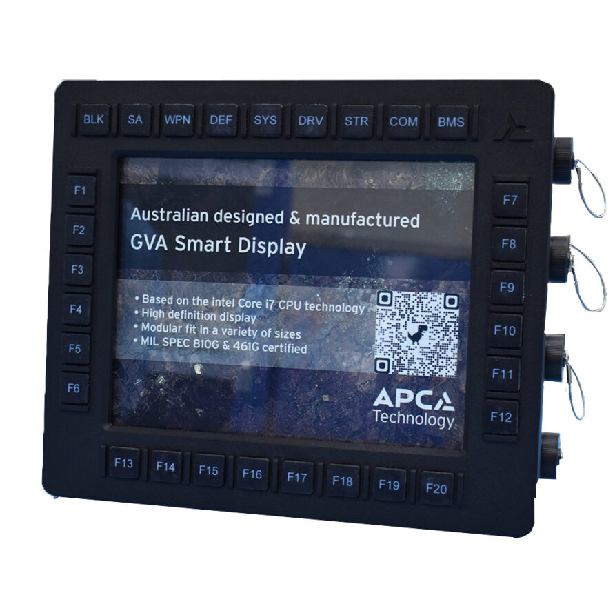
Like GVA, it exists in a wider framework, the Land Combat System Architecture (LCSA). It closely aligns with UK GVA.
Summary
It will be interesting to see how VICTORY, GVA and NVGA coexist, but ultimately, they are all about simplification.
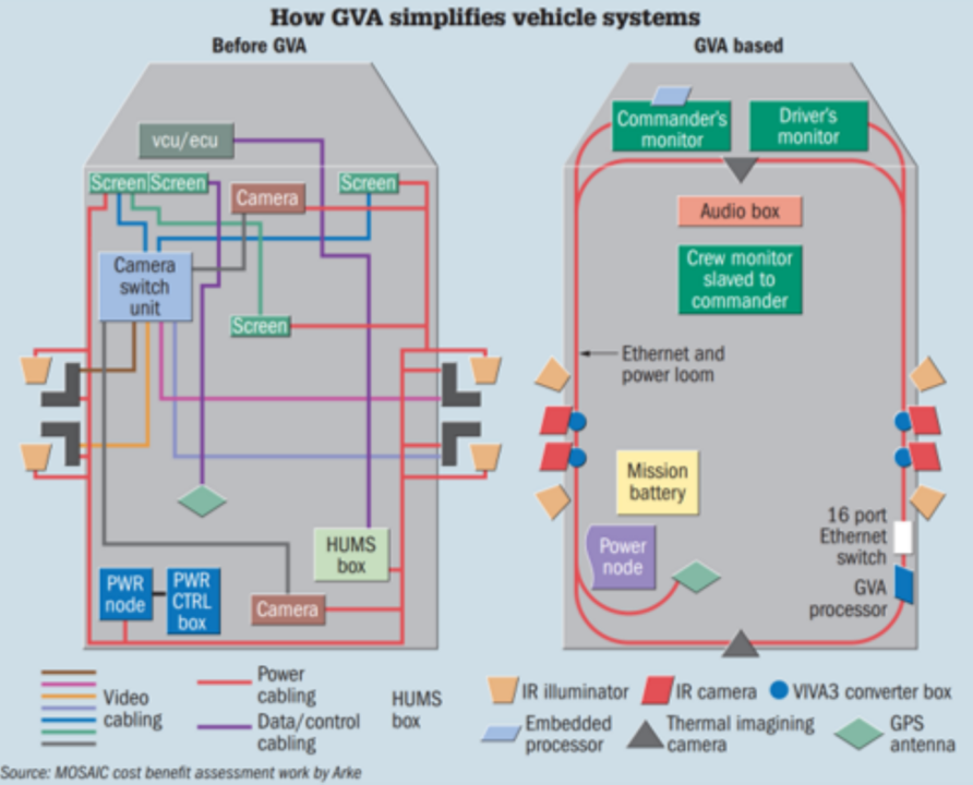
Not all the stated benefits may ultimately be realised but the MoD should be roundly congratulated for sticking to its guns on GVA and seeing it through, it creates a baseline for innovation and competition, avoids supplier lock-in and provides an enabling core for future expansion.
Shame no one outside the defence industry has ever heard of it.
Read more (affiliate link)

Discover more from Think Defence
Subscribe to get the latest posts sent to your email.


