
An examination of options for enabling offloading of the UK’s Strategic RORO vessels in existing ports without suitable RORO facilities
The previous articles on port enablement and operations have been wide-ranging, examining options for a survey, extensive repair and even building one from scratch in the manner of a modern-day Mulberry Harbour.
In comparison, this article looks at a narrower task;
How to offload a Strategic RORO vessel at a broader range of ports than currently.
and
Make everything needed to do so, able to be carried on a Bay class LSD(A)
Constraints and Objectives
The Strategic RORO vessels will provide the majority of seaborne lift for the British Army in most likely future operations.
Use one of these…
Landing Ship Dock (Auxiliary) – LSD(A)
Based on the Dutch/Spanish Enforcer class, four Landing Ship Dock (Auxiliary) replaced five Knights class logistics ships, entering service between 2006 and 2007; Cardigan Bay (2006), Mounts Bay (2006), Lyme Bay (2007) and Largs Bay (2006) [sold to Australia]

All three vessels are operated by the Royal Fleet Auxiliary, not the Royal Navy.
They are large vessels (16,160 tonnes displacement), much larger than the Knights class they replaced but have a relatively small crew of less than 60. The well dock is smaller than the Albion/Bulwark LPD’s but can still accommodate a single LCU Mk 10 or Mexeflote.


Smaller landing craft or workboats can be carried on deck and lifted to the surface by the 30-tonne capacity deck cranes. Mexeflote’s are sideloaded, one on either side of the hull.

Capacity includes 1,150 lane meters for vehicles and containers (20x 20ft ISO), 2,000-tonne cargo capacity and accommodation for between 350 and 700 personnel depending on overload conditions. Like the Albion/Bulwark class they have limited aviation facilities apart from a large helicopter deck but stores and vehicle capacity is greater, although landing craft capacity is much lower. Although they have a very large flight deck that can spot two Chinooks the aviation capabilities are relatively austere. To mitigate the lack of a permanent hangar they can be fitted with a Rubb hangar.

To enable the offloading of these…
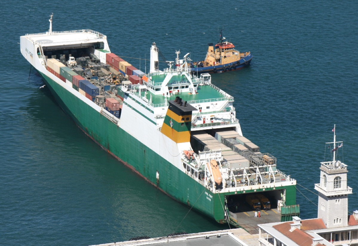
Strategic RORO Vessel
These are a Flensburger RoRo 2700 design.

All ships have the same characteristics except Beachy Head, Eddystone and Longstone that have more powerful 9 cylinder 8,100kw engines than the others, and therefore have a maximum speed of 21 knots; Hurst Point, Anvil Point and Hartland Point have a maximum speed of 18 knots. All have bow thrusters and a crew of 22. The ships are 193m long, 26 metres wide.
Their capacity is listed as 2,700 lane metres, trailer capacity is 35 on a tank top with a maximum height of 5m, 62 on the main deck with a maximum height of 6.8m and 67 on the upper deck with a maximum height of 6.8m. Container stowage capacity is 72 TEUs on the tank top, 272 TEUs (double stacked) on the main deck and 324 TEUs (double stacked) on the upper deck, all these on Mafi trailers. Direct stow container capacity is approximately 411 TEU with 60 10kw/32A reefer plugs available for refrigerated containers.
Access to the decks is via a side ramp and a 16.4m long by 17.0m wide stern ramp and internal ramps to all decks. The stern ramp has twelve 2.7m wide fingers to enable access to narrow link spans. None of the ramps is self-supporting but the stern ramp has a rated capacity of 85 tonnes and the side ramp, 75 tonnes. The deck crane has a capacity of 40 tonnes at 25m outreach and 36 tonnes at 28m outreach. Driver’s accommodation is in 6 two-berth cabins.
Constraints
Solutions have to …
- Facilitate the safe berthing and offload of a single Strategic RORO vessel at a time
- Maximise use of in-service equipment
- Have modest capital and resource costs
- Be able to be transported on a single Bay class LSD(A)
- Access the port from the LSD(A) without support from any port cranes or other infrastructure
- Be operable within the existing resource envelope as defined ay 24 Commando Engineer Regiment (RE), 17 Port and Maritime Regiment (RLC) and supporting elements from the RFA, British Army, Royal Marines and Royal Navy
One might argue this is more achievable and less indulgent (fantasy fleets) than previous articles on the subject.
Preparatory Tasks
Survey
A previous article covered port survey so I will just link it below.
Pier Repair
The same also applies to port repair, although the scope would be narrower than described in the previous article.
Options for Unloading the Strategic RORO Vessel
Under-keel clearance is another of those subjects that seem simple but aren’t. The ship may pitch and roll under the influence of tide, currents, wind and changes in load distribution and this has to be accommodated. The under-keel clearance figure will include allowances for squat, heel, wave and a safety margin. It can be a static or dynamic figure, the latter usually derived from in-situ environmental measurements and sophisticated software.
This will generally result in a working figure, including a safety margin. The Strategic RORO vessels have a stated draught of 8.6m so the working depth must be in excess of that. For the purposes of this article, have taken a figure of 0.6m and added a margin to get to a required depth of 9.5m., in practice, it may be more.
Option 1 – Existing Quayside or RORO Facilities
The most obvious answer is to use a ports existing facilities.
If a suitable landing ramp or linkspan is not available, if there is room, and the quayside wall is not too high, the ship could simply be ‘reverse parked’. This technique is often called Mediterranean Mooring or Med Moor as it is common in the area given the low tidal ranges.
It is not a simple technique and is limited to low tidal range ports, but is an option. Suitable mooring fixtures and tug support would also be a requirement.
Option 2 – Build an Expedient RORO Landing Slipway
In order to offload vehicles and cargo, the rear loading ramp is generally used and for many ports, nothing more complex than a concrete slipway is used for the ramp.

They can be of earth or concrete construction and fitted with mooring bollards, fenders and connecting roadways. If one of these is not available, it could be created from scratch. Traditional construction techniques usually require a watertight cofferdam to be built with sheet piling, sandbags or demountable barriers and dewatered. When the area has been dewatered concrete formwork and reinforcing are installed and infilled with poured concrete.

When the concrete has cured the barriers are removed. This makes for a sturdy installation but is time-consuming.
Purely in the interests of speed, alternative methods will be required.
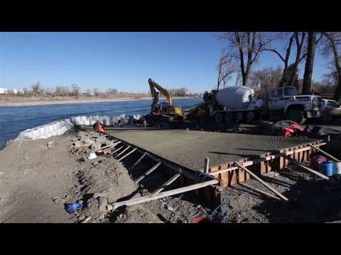
One of the possible methods to create a solid mass onto which a loading ramp can be lowered is simply to push granular material like gravel or hardcore into the water’s edge to create a sloping incline and then compact or secure it. This technique was used in Haiti in 2010 to enable large landing craft to offload RORO cargo.

It protruded into the water in order to provide sufficient under-keel clearance for the ship. The vessel in the image below is called the Cape Express which has a draught of 2.1m. The problem with this technique for the Strategic RORO vessel is simply one of scale.

Assuming an angle of repose of 30 degrees for loose-fill material, simple geometry results in a horizontal base of approximately 15m for a 10m height. This is a lot of fill material, so whilst it would certainly be possible to simply use fill material to create an expedient landing ramp, additional techniques might be needed to reduce the time and the angle (to prevent impingement on the ship steering gear for example)
If the angle cannot be reduced, the ship must move further from the ramp landing spot. The Strategic RORO vessels have a large ramp, 17m wide, 13.7m long, and with 2.7m flaps, this issue would need to be tested to determine whether it would be a significant problem or not. These simple calculations also, do not take into account ports with a significant tidal range.
Assuming an alternative to simple loose granular material is required, concrete cloth, prefabricated concrete mattresses or grout filled geotextiles are all options that could be tested for suitability.
Building the ramp gradient could involve a number of techniques, used together or alone. Pipe fascine bundles, Class 30 or 70 trackway and Hesco or Defencecell gabions are in service or in the defence supply chain and well suited to this type of temporary construction.
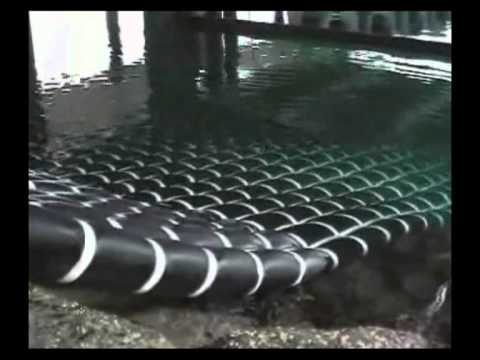
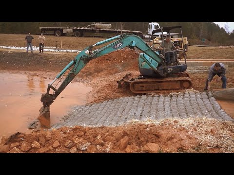
Marine grout is a special type of cement that is resistant to washout and able to cure in direct contact with water. Mixed with sand or small aggregates, it can be pumped into fabric bags or multi-cell mattresses. This type of installation is often used for scour protection and bank erosion control.

Because the fabric and concrete conform to the underwater and surface undulations and obstructions it would make an excellent ‘concrete carpet’ for landing craft and RORO ships.
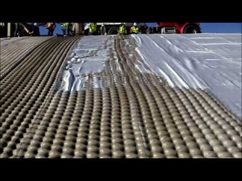
The problem with using cement and concrete is that it needs specialist mixing and pumping equipment, storage/transport of cement and sand/aggregates and time to achieve the required hardness after fill. Quick curing marine grouts are available but might not be suitable for this application and are still unable to achieve the required hardness in a reasonable time.
Lighter alternatives are available that are more commonly used in inshore erosion control such as Flexamat.
The innovative Concrete Canvas could also be used. Concrete Canvas is a British product that uses a concrete impregnated fabric on rolls of various lengths and widths. It is unfurled, secured using staples where required and hydrated. It can be hydrated by spraying with fresh or saltwater or simply immersed. After hydration, it achieves 80% strength in less than 24 hours.
Although Concrete Canvas has many excellent properties, it is relatively thin and so may not be durable enough for repeated trafficking, multiple layers may be needed but it is very easy to install so this would not be a significant barrier to use.
All these solutions would still need some form of base fill construction for the bulk of the ‘triangle’, and none are particularly quick given the time required to cure concrete or grouts.
These techniques may, therefore, be better suited to repairing or extending any existing ramps or creating new ones for shallower draught vessels.
Option Three – Build an Expedient Quayside Wall
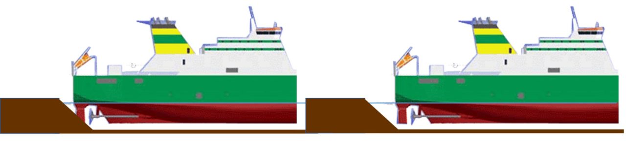
Instead of using loose-fill material with reinforcement, it might be better to simply build a quayside wall. Again, it all comes down to geometry, especially the underwater soil conditions, especially their gradients.
In the example below, there is a shallow gradient out to the required depth.
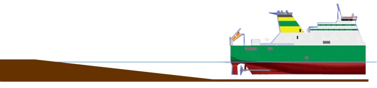
There are two options; excavate or fill
The first option would require sheet piling to be used and then the spoil in front of excavated using either long reach excavators or if possible, dredging.
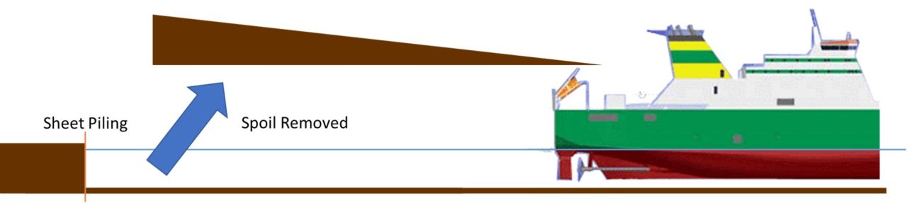
The second option would still require sheet piling to create a quayside wall, but it would be done to the right, and the void back-filled and compacted.
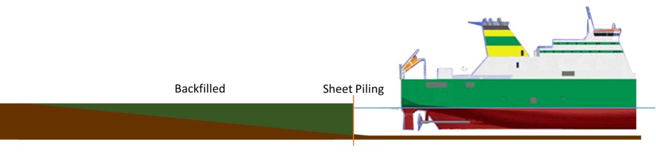
Both of these techniques are valid and selection would depend on a number of factors. If the gradient to the required depth is steep, again, either technique would remain valid but the volume of material to either remove or backfill will be much lower.
Non-pile supported piers and other port structures use sheet piling. The sheet piles are driven into the ground, secured using tiebacks and soldier beams and then backfilled.

The sheet piles are then capped, usually using concrete.

A more recent alternative is open cell bulkhead construction that uses sheet piles but arranges them in multiple U shapes to eliminate tiebacks and anchors. A Y shaped pile connector is used to form the U shape.

This technique may also prove to be useful for smaller installations, extensions and repairs.

Z and U shaped sheet piling continues to evolve but they are poor at dealing with vertical loads and so combination or high modulus walls incorporate sheet piling reinforced with tubular or box section piles. Concrete diaphragm walls are low maintenance and long life for deep draughts but require extensive construction excavation using equipment such as Hydrofaise cutters.
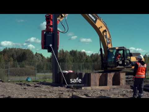
When driving sheet piles from the land side, the surface has to have sufficient bearing strength to support the pile driving equipment, this may not be present in the case of damaged areas and so driving from the floating platform may be the only choice available. This may require the use of a driving alignment frame, especially for crane supported devices.
Vibratory pile drivers liquefy the soil which allows the pile to be easily driven into the ground. They also reduce any transmitted vibration to neighbouring vulnerable structures, particularly where damage exists. For small repairs, a sheet piling attachment can be used with existing excavators although a dedicated leader rig would yield faster results at the expense of higher cost and transportability requirements. Typical of the dedicated hydraulic leader rig is the RG16T from RTG Rammtechnik GmbH. It has a telescopic leader and variable vibration for increased versatility and can install pairs of sheet piles up to 15m long. Setup times are usually less than 30 minutes once unloaded and their work rate is impressive. Auger attachments can be used to pre-loosen very hard soils.

One of these would be a very expensive addition and take up a lot of precious space on the LSD(A).
More reasonable, would be to use an excavator attachment.
A typical excavator mounted vibratory pile driver is the Movax Modular Side Grip attachment that can install piles up to 12m in length.
Although sheet piling would likely be the best option for creating a vertical wall, other solutions such as Geotubes or gabions might also be useful or as a compliment.
Tencate Geotube and Tele Teletextiles Teletube are two examples of geotextile tubes. Geotubes are flexible synthetic tubular containers that are fixed in place with tie rods and hydraulically filled with sand and water, under pressure. The sand is usually dredged from the surrounding area. Residual internal pressure forces the water out through the material leaving what is in effect, a gigantic sandbag. Dewatering chemicals can be used to accelerate the process.

They are used for slurry and waste dewatering and the construction of jetties, artificial islands, groynes, temporary dams, breakwaters, scour protection and beach erosion barriers.

Although full dewatering takes months, stability of the tube and load-bearing capacity can be suitable in a period of only ‘hours’. Multiple Geotubes can be stacked and filling carried out using multiple entry points with locally available non-cohesive sand and soils.

Geobags are smaller tubes closed at both ends in ready to deploy configuration.

What is especially attractive about geotubes in this context is their compactness in transit.
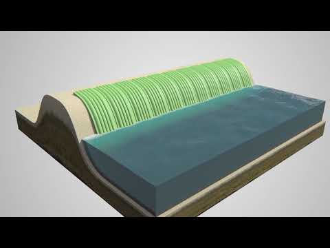
The main advantage of using geotextiles like the Geotube is their low weight and volume in transport, they are very efficient. Fill times will depend on many factors but a typical 2.5m high, 4m wide, 50m long Geotube with a medium-duty pump at 15% sand/water mixture will take 9 hours to fill.
Simply dumping boulders or precast concrete block into the sea at deck intervals would be the least complex but this would require a great deal of material and extended build times, neither desirable nor practical. Steel mesh gabions filled with rocks or cobbles can be lifted into place from a working platform with a suitable crane.

Built up to the required height they would form a sturdy wall that could be backfilled.

Again, the problem is one of time and available material volume, not insurmountable though.
A 20ft intermodal container has an internal volume of 29m3, with sufficient containers, it might be possible to build an expedient wall/jetty with these. Perforated and filled ISO containers could be used, weights would be higher but crane moves, and therefore time to install, significantly reduced. De-installation would also be very time consuming with solid concrete blocks or gabions.
Option Four – Bridging Trestles and Modular Bridge
This approach would require a trestle type support to be constructed and anchored to the seabed, with a panel type bridge launched onto it from the shore. It would completely negate the need for either backfilling or spoil removal.
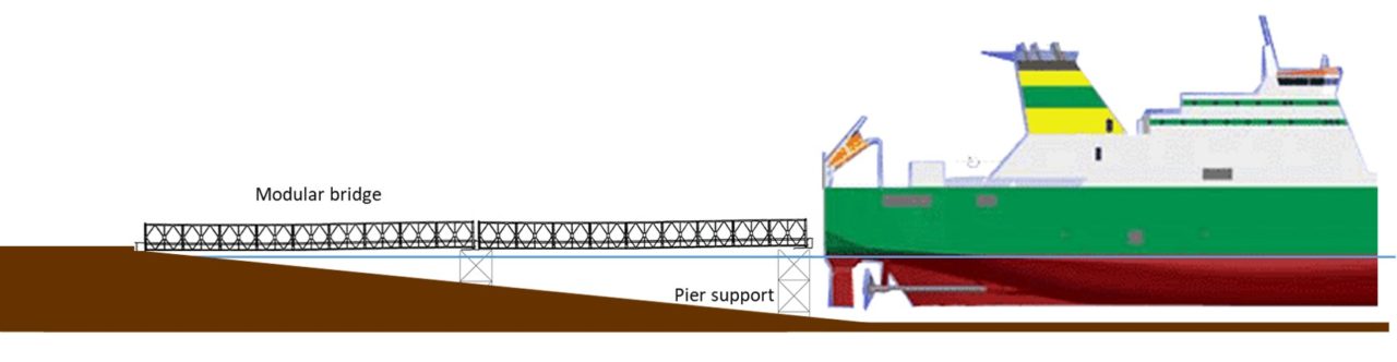
Any of the in-service military bridges could be considered for use, Mabey Compact 200/Logistic Support Bridge, Combat Support Bridge or even the Medium Girder Bridge. Bridge types not in service would also be considered, there are plenty of options.
Construction of the piers or trestles could be completed from the shore in smaller increments or if a single span bridge was possible, from a floating or spudded pontoon.
The MAT 75 is a modular bridge support system made from basic column units that are braced at either 5 or 10 feet centres with individual columns available in 2, 3, 4, 6, 8 and 12 feet lengths.

Adjustable screw ends and hydraulic jacks can be fitted on top of the columns to support the grillage beams that would support the pier deck. Pre-assembled units would simply be lowered onto the seabed and in order to provide additional bracing against wave loads, outriggers made from the System 160 shoring system could be fitted.

Whatever bridge pier support technique is used, it has to be lightweight and easy to assemble. The key requirement is a foundation of sufficient lead baring strength and scour resistance. Combinations of pre-cast concrete blocks, gabions, helical screw piles or geotextile could be used, depending on seabed conditions.
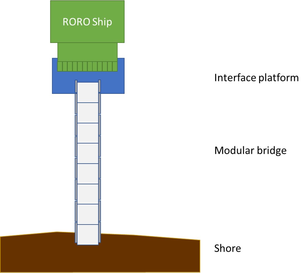
One of the main problems with this approach is the disparity between the bridge width and the RORO vessel ramp width. It would be subject to experimentation but it seems unlikely the vessel ramp would be ‘landed’ directly onto the end of a bridge.
More practical would be to enlarge the end pier such that both could be supported, creating an interface platform.
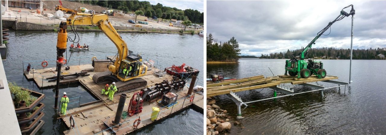
If prefabricated pier support trestles and an open interface platform are used, they may need to be secured with piles driven into the seabed soils. Conventional hammer driven piles are too time-consuming so if the soil conditions permit, helical screw piling is extremely fast in comparison. Increasingly used for low disruption and displacement piling on land there have been a number of examples of their use in road/rail infrastructure construction and proposals for offshore wind foundations, they were actually used commonly for Victorian piers, Brighton Pier for example and most motorway overhead signs are screw pile-supported.
A helical screw pile is as it sounds, a large screw driven into the ground using a hydraulic torque motor. Installation times are very low. Once driven, a tubular or sectional grillage can be placed on top and this is used to support the pier deck.
A grillage frame is shown below, something like this could be used for the interface platform if scaled up.

This arrangement has the potential to produce an extremely short installation time, and if used with off-board hydraulic power, one that can be used at deeper depths, nearer the pierhead, or, where ground conditions are suitable.
A similar underwater grillage frame with helical screw piling could also be used as a pier support as it can be driven into the undulating or sloping ground to level, making subsequent installation of support trestles much easier.
This technique is also now used for light-duty moorings.
Although this solution would not require a lot of earthmoving or sheet piling, it would still require a length construction process, lots of equipment and personnel. It also assumed this would take place in sheltered water.
Option Five – Deployable Linkspan and Modular Access Bridge
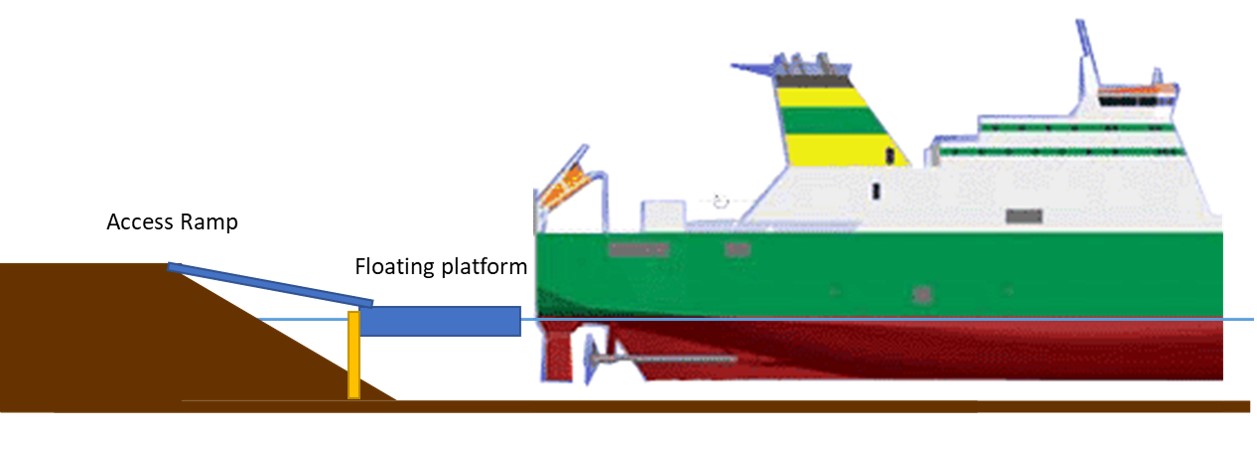
If a simple ramp or quayside wall is the first method of allowing a RORO ship to offload, a linkspan is the second. A linkspan is an intermediate device that evens out the different heights of the ship cargo deck/ramp and the quayside.
The mechanical support linkspan uses hydraulics to raise and lower the ramp onto which the RORO ships ramp is landed. The support housing is secured to the seabed using piles. Tidal range and different ship deck heights can be compensated by raising and lowering the deck and the more complex types have multiple ramps for fast loading and unloading of vehicles and foot passengers.
A floating linkspan falls and rises with the tide, the main structure being buoyant. Some ramp height variability can be accommodated using tank ballasting and they are usually of single deck construction, although some multi-deck floating linkspans are in use. The landing area and tank create a large water-plane resulting in good resistance to traffic loads.
They comprise two main components, the landing platform (usually incorporating the flotation tank) and connecting roadway.
To resist berthing loads, they tend to be piled
Linkpsans can be used in a number of configurations, depending on various factors.
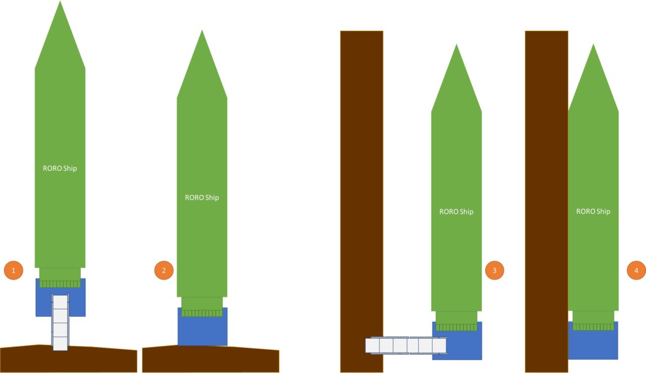
ONE; used where the bottom conditions are such that the floating platform needs a connecting ramp/bridge to the shore to accommodate differing heights between the floating platform and quayside.

TWO; used where the height of the quayside wall and the floating platform are the same, vehicles can be driven directly off the platform, often using a short interconnecting ramp.

THREE; Often used when the bottom conditions are such that the ship needs to be moored some distance from the quayside wall or where height differences are such that the bridge/ramp gradient would be unsuitable for vehicles due to traction or break over at the interface point leading to vehicles grounding.

FOUR; this is the ideal as it allows ships to make use of the quayside wall for mooring, berthing forces are not transmitted to the linkspan so it can be unpiled and no ramp would be required if the height differential is minimal.

Any deployable linkspan would be required to accommodate all four use scenarios or it would be of limited value. The already in service Mexeflote may be utilised as a linkspan. They support a load of approximately 10 tonnes per flote and can be fitted with spud leg carriers from Jenkins Marine.
Mexeflotes have been demonstrated as floating supports for the Strategic RORO vessels outside of a port environment

Many years ago, the same was also demonstrated with the larger G3 Atlantic Conveyor design, although the G3’s had a self-supporting ramp.

Mexeflotes, therefore, are a potential option, especially as they are in service, can be sideloaded on a Bay class LSD(A) and easily adapted with rails and spud leg carriers. The question mark with Mexeflotes would be their ultimate load capacity, certainly worth experimenting with though.
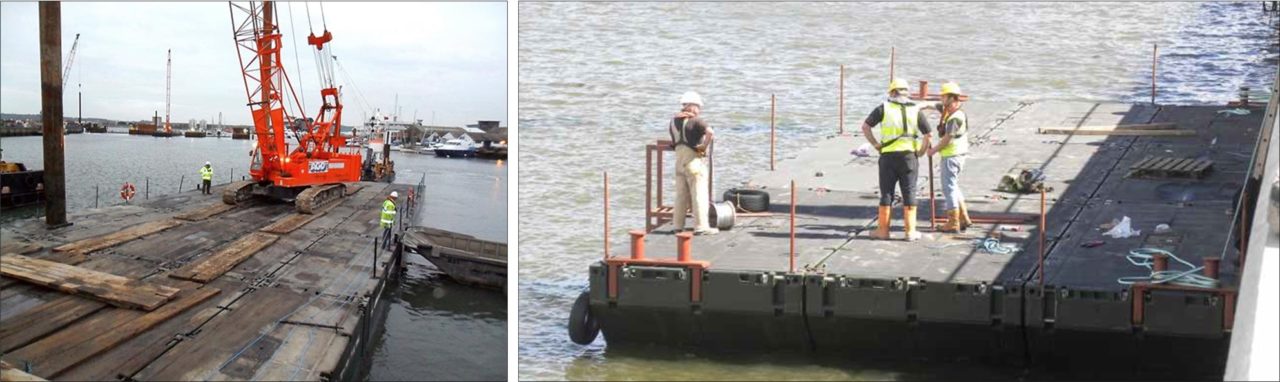
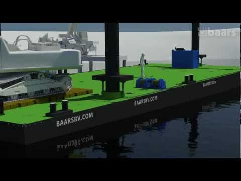
To accommodate greater loads or ramp/wall height differentials, larger modular pontoons are available from many different manufacturers, including Volker Brooks, Janson Bridging, Damen, Hann Ocean, Robishaw Engineering, Combifloat, Modular Pontoon Systems, Intermarine, Innovo, Baars, Poseidon Barge and Ravenstein.

These larger ISO container-sized pontoons often have a very wide range of accessories and applications.
Incredibly versatile, they can be used as work platforms, dredgers, ferries, jetties, rafts, causeways and linkspans.

All similar, generally ISO container-sized steel boxes with a range of accessories such as lifting spuds, rails, decking, bollards, fairleads, ramps and connectors. They are transported to the work area, lifted into the water using cranes and connected together using various locking mechanisms, pins and other connectors.

A 40ft x 8ft x 8ft ISO container-sized pontoon can support a maximum of 50 tonnes with a freeboard of only 30cm.
They can be towed, pushed or propelled using Thrustmaster type units, as found on the Mexeflote, the OD15N in particular. In the context of a requirement where everything has to fit inside or on the deck of an LSD(A), these might be carried inside the well dock and towed into position using Army workboats or fitted with Thrustmaster type propulsion units.
To provide greater stability and to resist berthing forces, the floating pontoons can be stabilised using spud legs. All the pontoon manufacturers offer freefall spud legs in a variety of lengths and end cap designs.

The linkspan pontoon would still float up and down, but the spud legs would limit this movement to the vertical plane only, reducing the need for anchors and twisting or rolling movement.
If the seabed provides sufficient load-bearing strength the spud legs can be used to support deck loads in addition to providing stabilisation. There would still be no driving as the freefall may provide sufficient seabed penetration load-bearing penetration. Jacking units can be attached and the pontoon jacked up, either completely clear of the water surface or partially clear, or semi-submerged.
In some locations, there will be a height differential between the modular platform and quayside or pier deck. Without some form of ramp or roadway, vehicles will not be able to be offloaded so the solution must also have some form of the adjustable ramp that can also accommodate the same MLC 120 loads as the landing platform. It will also require an interface for both the platform and quayside that prevents slippage and adjusts for differing angles as the tide changes.
This connecting ramp could be constructed using BR90 or Logistic Support Bridge There will be a number of cranes available within the port environment so as long as it fits within the weight and reach envelope of a Terex AC55 it should be quick and easy to lift into place.

Additional Considerations
Vessel Manoeuvring
Moving ships in turning basins and mooring areas requires the use of tugs, even for those that have bow thrusters like the Strategic RORO vessels. The RLC Army workboats can be used as tugs but whether they have sufficient power for the Strategic RORO vessels would need testing.

They are 14.75m x 4.3m, weigh 48 tonnes, have a top speed of 10 knots and are equipped with firefighting equipment. When deployed they are usually carried as deck cargo on a specially designed cradle and craned to the surface as needed. If no harbour tugs are available in the port, it might be a requirement to purchase one as part of this solution.

Fendering
Fendering systems provide protection for vessels and pierheads. Pneumatic fenders, high-density foam and other systems can be fitted to the sides of the linkspan.

It would be sensible to include a number of these within the overall stores’ package just in case none were available at the port.
Mooring
There are a number of different types of mooring bollards with selection depending upon factors such as mooring angles, number of lines and required load strength.

Installation generally uses cast in or through deck bolts and resin anchors are used for retrofit applications. As with fenders, including a number of retrofit bollards and the necessary fixing consumable would be a sensible addition, together with various lines.
Localised Repairs and Small Construction Tasks
For small repairs to existing ports, fixing additional bollards and building expedient RORO ramps and quayside walls, some extra plant and equipment might be needed, although the vast majority is already available in the C Vehicle fleet.
Quaysides may need temporary repair or reinforcement, piles and mooring fixtures can also be damaged to an extent that stops the port from being of use. Any repairs need only be ‘good enough for the duration of the operation and so temporary measures are perfectly OK.
Existing RE/RLC dive equipment is perfectly suited for the port environment, the subsurface environment is complex and especially dangerous in ports so the full range of rescue and standby equipment will be needed, as would ‘polluted environment’ equipment, ports are generally not the most pristine of waters to dive in. Underwater cutting equipment and power tools are in service including Broco cutting torches and Stanley underwater hydraulic diamond chainsaws for example. These should be augmented with additional specialist equipment such as steel wire rope and rebar cutters.
A diver ‘cage’ would be a useful addition to the equipment pack, used from a wheeled excavator or mobile crane.

In addition to portable ladders and other access equipment, the divers will need a floating work platform. This platform can also be used for many other tasks. The easiest way to provide a floating temporary work platform in relatively sheltered water is to use one of the many modular pontoons available in the commercial market, steel or plastic.

HDPE modular pontoons are cheap, easy to deploy, adaptable, maintenance-free and available from many suppliers such as Airfloat, EZ Dock, Pontoon Works, Versadock and Aqua Dock, to name but a few.

They can be fitted with a range of accessories such as cleats, rails, deck covers, utility connectors and connecting modules. Surprisingly robust, when assembled they can be used as work platforms, temporary bridges, jetties, drive-on boat docks and docking interfaces.

Some additional excavator attachments might prove beneficial, hydraulic breakers, sweepers, shears and grapples for example.

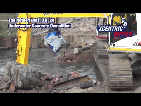
Specialist demolition equipment such as pulverisers, drum cutters, demolition grabs and rippers may also be used for greater efficiency. Because the debris might be timber or wooden piles excavator mounted saws would also be very useful.
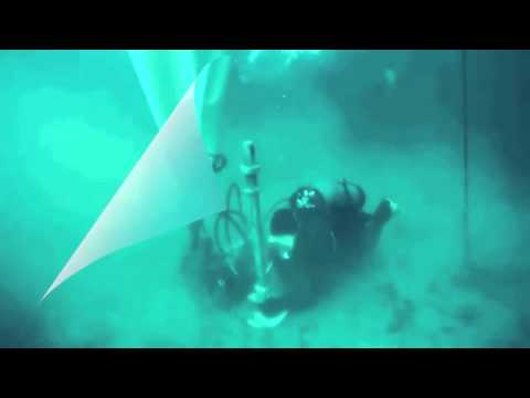
Decks are often mounted on concrete, steel or timber piles and if these are damaged or degraded their ability to withstand berthing forces and mechanical handling equipment is greatly compromised. The image below shows just such a repair task being carried out by US Navy divers in Port au Prince in the aftermath of the 2010 earthquake

Traditional pile repair techniques involved dewatering the surrounding area but new methods have long since replaced those and the most common method now used involves creating a temporary jacket using fibreglass or fabric forms and filling the cavity with marine repair epoxy, after removing friable or rotten material. There are a number of British, European and International standards that can be referenced and modern systems tend to comply with the provisions of all of them.

Most of the commercial systems are designed for permanent repair and require all friable, corroded or rotten materials removed using high-pressure water or physical abrasion before applying the jacket but given the time constraints involved, this may not always be possible.
Pilejax from the Australian company Joinlox is a relatively new system that combines ease of installation with low cost. Available in a number of lengths and diameters it uses an innovative locking mechanism and seals combined with flat-pack FRP sheet forms. It is, therefore, space-efficient and lightweight, making it attractive for this requirement.
Other systems are available.

A stock of Pilejax could be held in a single container, together with a stock of marine epoxy repair compound and appropriate hoses, pump and mixing equipment such as those from Putzmeister.

Concrete and tarmac repair products are widely available and can be used for small areas but where large areas need repair a graded fill material will be needed. If rubble is available and has been converted to graded granular fill material it can be recycled and reused for this purpose. Dredged sand can be recycled although if settling lagoons are used it might not be in a suitable form for several days. Otherwise, local purchases may be the only practical alternative.
The in-service Class 30 or 70 Trackway may also be used but alternative products such as fibreglass and composite road mats may be more applicable as the underlying surface is still load-bearing and are now widely available, very easy to use, lightweight and have a low scrap value meaning they are less likely to be stolen. Rolatrac i-Trac, Matrax HD and Oxford Plastics Roadplate are representative products.
Aggregate and infill materials would be transported by the Iveco Medium Dump Trucks described above although if available, smaller Terex TA3, or Dumper Ultra Light, might also be used for smaller loads. Excavator mounted hydraulic compacter plates could be used if the roller and vibratory compactors were not available. It is a swings and roundabouts decision, less to deploy but when the excavator is compacting it is not excavating.
The ubiquitous JCB 4CX or tractor Wheeled Light would no doubt find a role in general repair work. Bomb cratering or damage as a result of earthquakes will produce holes and cracks that need filling (stop giggling at the back!).
Processing concrete, rock and masonry rubble into graded fill avoid having to ship it in or purchase locally, this would be especially useful if one of the methods described above for the RORO ship required a reasonable quantity of graded fill material.
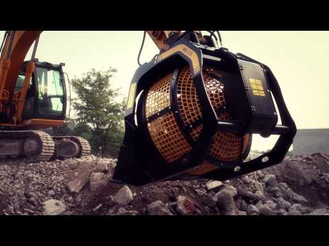
For small gap filling requirements rubble can be processed in-situ using a combination of bucket crushers and rotating sorters. These are attachments for existing excavators widely available from a number of manufacturers such VTN Europe and MB Crusher.
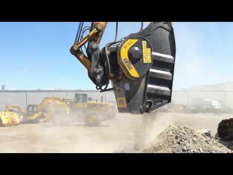
By processing in-situ stockpiling and transport is reduced.
If larger quantities are needed then the excavator mounted devices will not have the capacity so a dedicated unit might be more appropriate. Concrete recycling equipment can vary in size from mini-units designed for domestic applications that fit through a doorway right up to large semi-permanent units with high throughput. A typical medium-sized unit is the RM 70GO! from Rubblemaster that can process up to 120 tonnes per hour with variable output sizes.
Expanding on the modular steel pontoon approach used for a deployable linkspan allows the creation of multiple vessel types. Simply carrying a couple of extra pontoons and adding a wheelhouse and deck crane would provide the necessary stability and reach for buoy handling. Using two modules wide creates the 1205 and three wide, 1908.

These could be used for a wide range of enabling tasks.
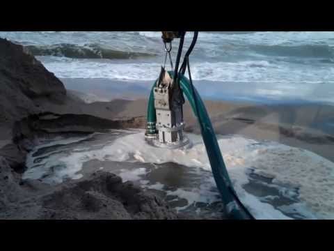
Dredging and Debris Removal
The working assumption is that dredging would not be in this requirement as it is a specialist task that is generally time-consuming. More details are included in the more expansive article on port repair. However, some minor sunken debris removal or localised dredging might be possible with a long reach excavator.

They are most suitable for unconsolidated soils containing pebbles, clay and sand, and friable or crumbly rock. In conjunction with float bags and chain hooks, might also be used for debris or small wreck removal.

In addition to a bucket, a long reach excavator could be fitted with a dredging pump. A long reach excavator is no different to any other, it simply has a longer articulated arm, and thus, it is not especially specialised.
If there is any floating debris such as insulated containers, logs or small craft they can be pulled out of the way using workboats and ground-based winches. The in-service CAT D5N can be equipped with a winch, useful for such application, an example shown below, also in Haiti.


Summary and Thoughts
The vast majority of the capability to survey ports and conduct small repairs and debris removal already exist. We might purchase some additional items to enhance these existing capabilities such as pile repair products, marine grout handling equipment, dive platforms and specialist excavator attachments, but none of these is particularly expensive or difficult to maintain.
That is not to say it would be easy to uplift existing capabilities, but there is a route there that exploits commercially available equipment and supplies, nothing is cutting edge or even new.
What would need some experimentation is the ship to shore interface.
I don’t know whether a simple ramp would be possible to generate that would work, we would need to try it. Beyond that, we start to look at more expensive solutions such as sheet piling or modular pontoons and modular bridging.
That said, modular pontoons are just empty metal boxes, they are not F-35’s.
Without doing specific calculations, I also think it is perfectly feasible to carry everything needed for this modest task on or in an LSD(A). Whether one would be available is another matter but in the context of this series of articles…
WE NEED TO GIVE PORTS MORE PRIORITY
Table of Contents
Share on twitter
Twitter
Share on facebook
Facebook
Share on linkedin
LinkedIn
Share on reddit
Reddit
Share on whatsapp
WhatsApp
Additional Reading
Anchor installation using screw piling
Mabey propping and jacking brochure
The design of ship-to-shore linkspans for ro-ro terminals
Navy Lookout article on the Bay Class LSD(A)
Change Status
| Change Date | Change Record |
| 01/03/2017 | initial issue |